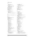
SETTLING, 3-26, 3-27, 4-19, 4-20
TESTED, 3-26, 3-27, 3-28, 4-19, 4-20,
4-21
TRIGGER, 3-27, 3-28, 4-20, 4-21
static RAM, 5-10
status LEDs, 5-7, 6-5, 7-5
status register, A-5
summer, 6-2
Support, ix
Support Resources, ix
sync/trigger line, 3-25, 3-26, 3-27, 3-28,
4-18, 4-19, 4-20, 4-21, 5-13
synchronization
multiple-mainframe, 3-14, 4-17
TTLTRG, 5-13
synchronous sampling, 5-2
SYSRESET*, 5-8
system requirements, 2-3
T
Tach1, 7-5
Tach2, 7-5
tachometer
block diagram, 7-3
edge trigger, 3-29, 4-22
features, 5-2
parameters, 4-9
tachometer input, 7-2
tachometer monitoring, 7-2
tachometer option, 7-2
Technical Support, ix
TESTED state, 3-26, 3-27, 3-28, 4-19, 4-20,
4-21
transferring data, 5-9
trigger, 3-15, 3-29, 4-22, 5-2
analog, 7-2
arbitrary source, 6-2
auto, 3-29, 4-22
external, 3-29, 4-22, 5-13, 5-14, 7-2
input, 3-29, 4-22
LED, 5-7
lines, 5-13
manual, 3-29, 4-22
source, 3-29, 4-22
tachometer edge, 3-29, 4-22
TTL, 5-13, 7-2
Trigger LED, 7-5
trigger level, 3-31, 7-2
TRIGGER state, 3-27, 3-28, 4-20, 4-21
triggering
exact RPM, 7-2
troubleshooting, 9-2
TTLTRG lines, 5-13
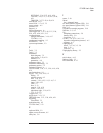
U
up/down RPM, 5-2
update source firmware, 6-5
utility bus, 5-8
V
veetest, 2-10
Vibrato
See 4-channel input
view detail button (Agilent VEE), 2-11
view panel button (Agilent VEE), 2-11
VISA, 2-3
Visual Basic example programs, 2-19
VME Bus, 5-2, 5-9
VXI
backplane connections, 5-8
button (SFP), 2-9
Local Bus, 5-2
VXI Bus, 3-9, 4-12, 5-10, 5-14
dynamic configuration protocol, A-5
registers, A-5
VXIplug&play
driver, 2-5, 2-6, 3-3, 3-6
help, 3-39
overview, 3-3
VXIplug&play library, 2-3
W
wait for done, A-13
Windows Help, 3-5
write command, A-12
VT1433B User's Guide
Index


