


Trigger Lines (TTLTRG)
TTLTRG consist of eight TTL lines on the VXI backplane on connector P2.
They are available to provide synchronization between devices. VXI devices can
use the TTLTRG lines for simple communication with other devices. For
example, a device can wait for a line to go high before taking an action or it can
assert a line as a signal to another device.
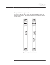
The VT1433B uses two trigger lines. These can be placed on any two of the
eight TTLTRG lines available on the VXI backplane. The lines are:
q
Sync/Trigger line
q
Free-running clock line
When programmed in a multiple-module configuration, only one of the VT1433B
modules can provide the clock signal but any of them can trigger.
VT1433B User's Guide
Module Description
5-13
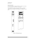
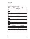
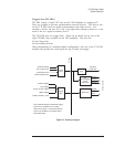
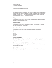
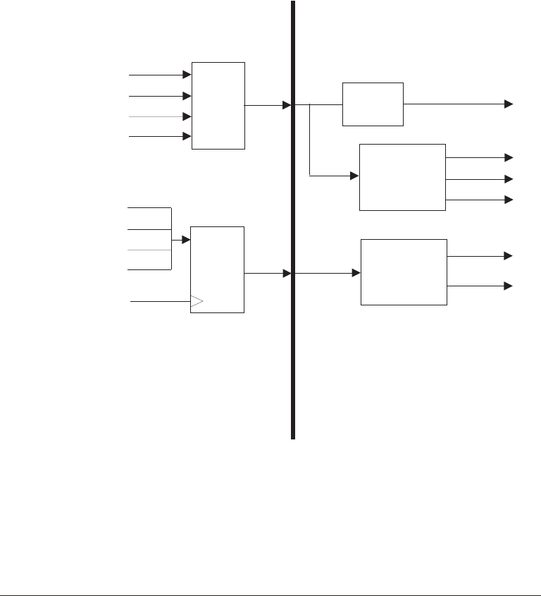
External Sample
Clock
MUX
Trigger
Sync
Gate Array
Trigger
Sample 1
Sample 0
(word rate)
Sample 0
Logic
Sample 2
Sample 3
Sync
PPL
Oversampled
Clock
Generator
Note: External Sample and External Trigger
inputs are not available on VT1433B’s
with a source option. The External Sample
input is not available on VT1433B’s with a
tachometer option.
VXI 10 MHz Clock
24.576 MHz Clock
10 MHz Crystal Clock
External Trigger
Input Trigger
Source or Tach Trigger
96002 Trigger
10 MHz, Sample 0, none
to in
p
ut circuits
VXI bus
Figure 5-5: Clock/sync diagram