


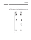

Status LEDs
q
Fail: This is the standard VXI “Failed” indicator. It lights briefly when powering up
and normally goes out after a few seconds. If it stays on it indicates a hardware failure
in the module.
q
Acs: This is the standard VXI “Access” indicator. When it is on, it indicates that
another device on the bus is contacting the module, for example to transfer data or read
registers.
q
Trigger: This LED flashes on each time the measurement triggers, so when it is
blinking it indicates that the measurement is triggering.
If the VT1433B has the Tachometer option, this LED is defined differently. See the
chapter: The Tachometer Option (VT1433B-AYF).
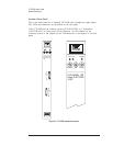
SMB Connectors
q
FExSamp: This is an input connector for an external sample clock. The sample clock
must be TTL level and have a frequency between 40.96 kHz and 100 kHz. Internally
this frequency can be decimated.
q
Cal: This connector is used for calibration. It can be configured to output a calibration
signal or to accept an input calibration signal. See the calibration section in this
chapter.
q
ExTrig: This allows for an external trigger input to the VT1433B. The input signal
must be TTL, other characteristics can be defined in software. ExTrig can be enabled
or disabled in software.
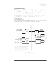
Input Connectors (One or Two)
These connectors are attached to the cables from an 8-Channel Input (breakout
box). They connect the input signal to the VT1433B. Each connector carries
four channels. Depending on options, there can be one or two input connectors
(four or eight channels).
VT1433B User's Guide
Module Description
5-7