


q
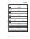
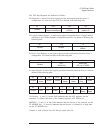
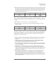
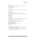
IRQ Status Register: This read-only register indicates the reason for asserting the VME
Bus interrupt. The format of the data is identical to that of the Status/ID word returned
by an interrupt acknowledge (IACK) cycle. It differs from the IACK cycle in that the
IACK cycle will clear the status bits and cause the de-assertion of the IRQ line. The
register has the following format:
Bit 15-8 7-0
Contents Status
Logical
Address
Status: Each of these bits indicates the status of a cause of interrupt. A one (1)
in a bit position indicates that the corresponding source is actively requesting and
interrupt.
Logical Address: This is the device’s current logical address.
q
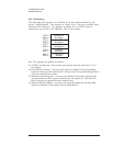
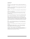
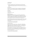
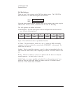
IRQ Reset Register: This register is used to resent the interrupt function. It has the
following format:
Bit 15-8 7-0
Contents
Reset
Bits
Unused
Reset Bits: Writing a one (1) to any of these bits will clear the corresponding bit
in the IRQ status register. This will not disable subsequent interrupt generation.
Clearing all of the IRQ status bits will cause the de-assertion of the IRQ line.
Writing a zero (0) has no effect.
q
Ram 0-1: These are 32-bit general purpose RAM locations which are also accessible to
the on-board DSP. See the following section regarding D16/D08 access of 32-bit
registers.
q
Send Data Register: Reading this register gets the next available word from the
measurement data FIFO. The measurement data FIFO is a 32-bit device. See the
following section regarding D16/D08 access of 32-bit registers.
q
Receive Data Register: Writing to this register puts a word into the source data FIFO.
The source data FIFO is a 32-bit device. See the following section regarding D16/D08
access of 32-bit registers.
q
Count Register: The Count register contains an unsigned 16-bit integer which is the
number of 16-bit words of data which are currently available from the Send Data
register or which the Receive Data register is currently ready to accept. While a device
is generating or accepting data, the Count register may indicate fewer than the actual
number of words available.
q
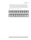
Query Response/Command Register: This register is used to send commands to and
receive responses from the device. It is implemented as a 32-bit RAM location.
Writing the least significant byte (highest address) clears the Command/Parameter
Ready and Query Response Ready bits in the status register and interrupts the on-board
DSP. See the following section regarding D16/D08 access of 32-bit registers and the
communication protocol.
VT1433B User's Guide
Register Definitions
A-9