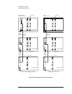
All modules need to be set to use the shared sync line rather than the default
setting of internal sync. This can be done with the e1432_set_multi_sync
function, using the group ID.
One module of the set of modules needs to be set to output the sync pulse. The
module with the lowest VXI logical address is called the “system module” and
assigned this duty. This can be set with the e1432_set_multi_sync function call,
using the lowest channel ID in the group (NOT the group ID).
All modules except the “system module” need to be set to use the VXI TTL
trigger lines as the clock source. Use e1432_set_clock_source for this.
Set the “system module” to output the clock. Use e1432_set_clock_master for
this. After this is done, all system sync pulses come from the “system module”
and drive the measurement state machines on all boards in the group.
Possible Trigger Line Conflict
The following describes a scenario where VT1433B modules might conflict and
prevent a proper measurement. The conditions allowing the conflict are complex
but must be understood by the user.
After a measurement has completed, the modules are left set up. If a module
(call it module ‘A’) is driving the TTL trigger lines and a different group is
started which also drives the TTL trigger lines (and that different group does not
include module ‘A’), then module ‘A’ will conflict and prevent the other group
from functioning. In this case make a call to e1432_finish_measure (using the
old group ID which includes ‘A’) to turn off module ‘A’ and allow the new
group to function.
Note that if the new group includes all modules of the old group, the conflict will
not occur since e1432_init_measure will reset all modules as needed. Also note
that single module groups do not drive the TTL trigger lines, so single modules
groups are immune from causing or receiving this conflict.
VT1433B User's Guide
The Host Interface Library
4-13


