


In the BOOTING state, the digital processors of the module load their parameters
and their program. Once done, the module releases the Sync/Trigger line and
moves to the BOOTED state. The VT1433B stays in the BOOTED state until it
sees a high-to-low transition of the Sync/Trigger line (that is, all the VT1433Bs in
the system have booted).
In the SETTLING state, the digital filters are synchronized and the digital filter
output is ‘settled’ (it waits N samples before outputting any data). Once the
module is settled, it advances to the PRE_ARM state.
In the PRE_ARM state, the module waits for a pre-arm condition to take place.
The default is to auto-arm, so the module would not wait at all in this case.
When the pre-arm condition is met, the module releases the Sync/Trigger line and
advances to the IDLE state.
This complete measurement sequence initialization, from TESTED through
BOOTING, BOOTED, SETTLING, PRE-ARM and IDLE, can be performed with
a call to the function hpe1432_initMeasure.
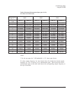
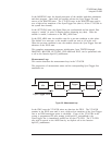
Measurement Loop
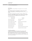
This section describes the measurement loop in the VT1433B.
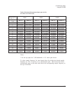
The progression of measurement states and the corresponding Sync/Trigger line
transitions are:
In the IDLE state the VT1433B writes no data into the FIFO. The VT1433B
remains in the IDLE state until it sees a high-to-low transition of the Sync/Trigger
line or an RPM arm/trigger point is calculated. If any of the VT1433Bs in the
system is programmed for auto arming (with hpe1432_setArmMode), the
Sync/Trigger line is immediately pulled low by that VT1433B. The VT1433B
may also be moved to the ARM state by an explicit call to the function
hpe1432_armMeasure.
VT1433B User's Guide
Using the VT1433B
3-27
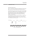
MeasureIdle
Sync/Trigger Line
Arm
Trigger
LH
LHLH
L
H
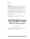
Figure 3-9: Measurement loop