


89
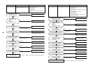
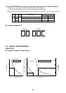
7-6. 7-Segment Display Function
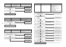
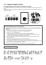
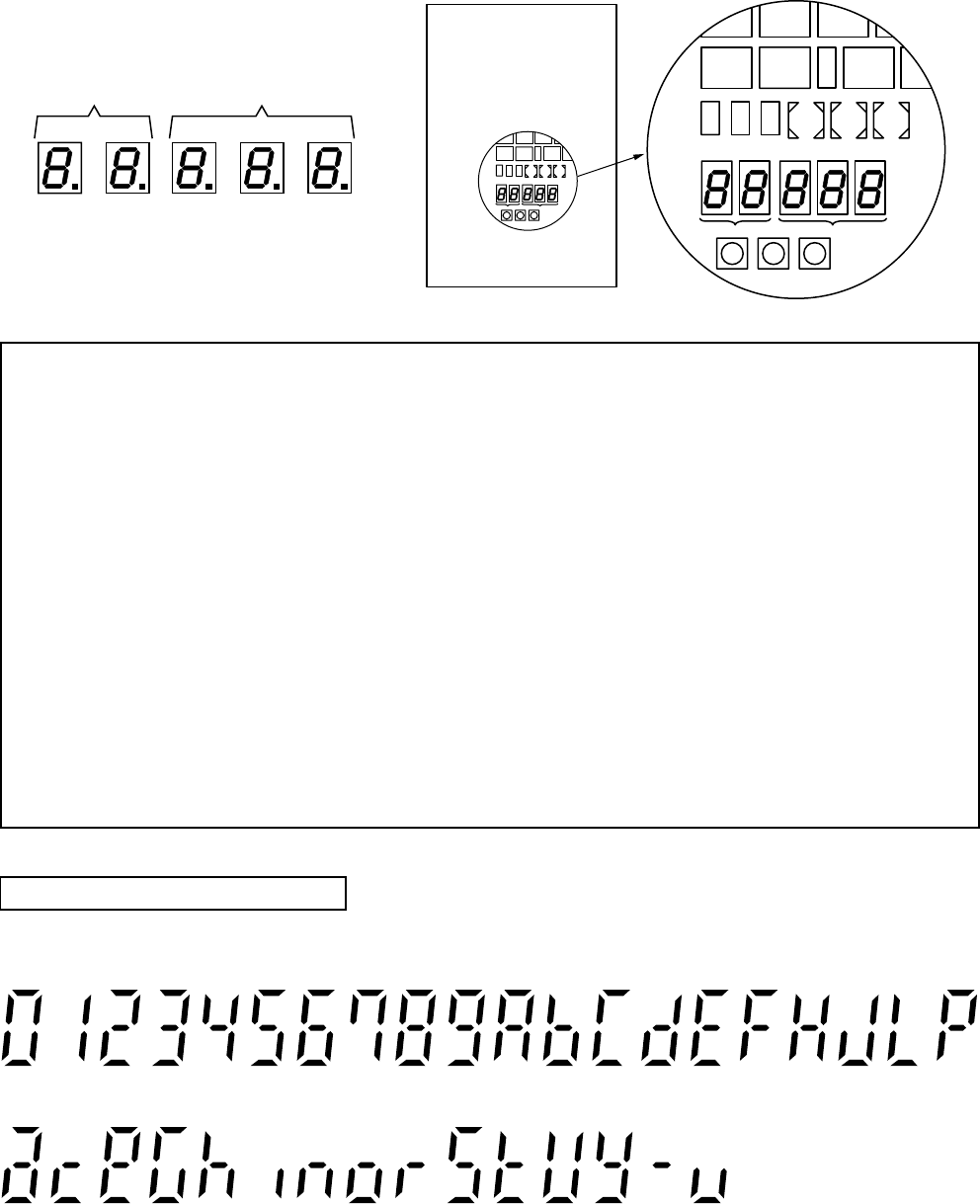
n 7-segment display on the outdoor unit (Interface P.C. board)
On the interface control P.C. board, 7-segment LED to check the operating status is provided on the control P.C.
board.
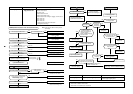
The displayed contents are changed by combining the setup numbers of the rotary switches (SW01, SW02, and
SW03) on P.C. board.
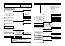
u Check procedure in case of stop with trouble
When the system stopped due to a trouble of the outdoor unit, execute a check in the following
procedure.
1. Open the panel of the outdoor unit, and then check the 7-segment display.
The check code is displayed at the right side of 7-segment display B.
[U1] [¡¡¡] ([¡¡¡]: Check code)
∗ Switch setup when confirming the check code: SW01 [1], SW02 [1], SW03 [1]
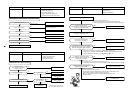
However the check code [¡¡¡] is displayed for 3 seconds and the auxiliary code [¡¡¡] for 1
second are alternately displayed if an auxiliary code is provided.
2. Confirm the check code, and then conduct the check operation based on the procedure of each
check code diagnosis.
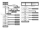
3. [U1] [E28] on 7-segment display means a trouble on the follower unit.
Push the push-switch SW04 on the header unit for several seconds. (2 seconds or more)
As only the fan of the outdoor unit with a trouble drives, open the panel of the corresponding unit, and
then confirm the check code displayed with 7-segment.
4. Perform the check operation based on the procedure of each check code diagnosis.
2nd.
place
1st.
place
7-segment
display A
7-segment
display B
3rd.
place
2nd.
place
1st.
place
D602 D603 D604D600
CN30
SW08SW06
CN31
CN32
SW04
D601
SW01
Display A
Display B
SW02 SW03
SW05 SW15
SW07 SW09
D602 D603 D604D600
CN30
SW08SW06
CN31
CN32
SW04
D601
SW01
Display A
Display B
SW02 SW03
SW05 SW15
SW07 SW09
Interface P.C. board
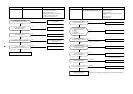
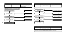
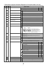
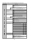
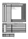
How to read the check monitor
<7-segment display>
a
0
c
1
e
2
G
3
h
4
i
5
n
6
o
7
r
8
S
9
t
A
V
b
y
C
–
d
u
EFHJLP