


25
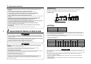
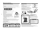
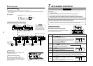
Thermal insulating process
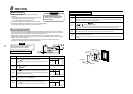
• After checking of the draining, using the supplied thermal insulation fit to the flexible hose leaving no clearance at
the connecting port of the indoor unit.
• Fit locally procured thermal insulation to the drain pipe leaving no clearance between the supplied insulation.
Flexible hose
Hose band
Attached heat insulator
Heat insulator to be
procured locally
Hard vinyl chloride pipe
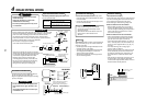
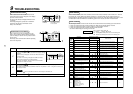
CAUTION
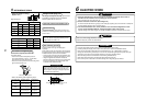
Ensure water is poured slowly.
To reduce risk of water spreading throughout the
unit, resulting in a possible fault.
4
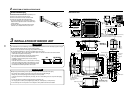
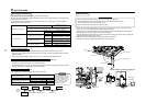
DRAIN PIPING WORK
Water (1500cc to 2000cc)
Insert the leading part of the
hose between the heat
exchanger and the drain pan,
and then bend it downward.
Check panel
Polyethylene hand pump for
pouring water in drain pan
Vessel
Drain pan
Air
discharge area
5
REFRIGERANT PIPING
WARNING
• If refrigerant gas leaks during the installation work, ventilate the room immediately.
• If the leaked refrigerant comes in contact with fire, noxious gas may generate.
• After the installation work, confirm that refrigerant does not leak.
• If refrigerant gas leaks into the room and flows near to a source of fire, noxious gas may be generated.
REQUIREMENT
When using long length of refrigerant piping. Provide support brackets at intervals of 2.5 m to 3 m.
If the pipes are not fixed abnormal sounds may be generated.
Ensure the supplied R410A flare nuts are used.
Permissible pipe length and permissible height difference
This differs depending on the outdoor units. For details, refer to the Installation Manual supplied with the outdoor
unit.
Piping material and dimensions
• Use new and clean pipe, ensuring that the pipes are not contaminated with dust, oil, moisture, etc.
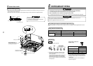
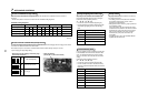
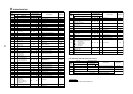
Pipe flaring
Flaring
1. Cut the pipe with a pipe cutter.
2. Place flare nut onto the pipe, and flare the pipe.
(Use the flare nut fitted to the unit or one that is
R410A compatible)
As the flaring sizes of R410A differ from that used
on R22. It is recommended to use a dedicated
R410A flaring tool. However a conventional flare
tool can be used, by adjustment of the projection of
the copper pipe.
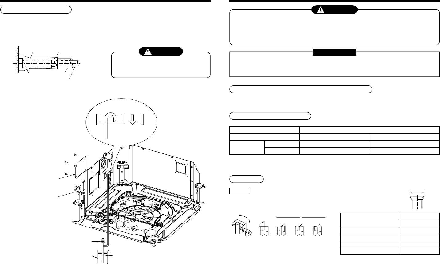
• Flaring diam. meter size :
A (Unit : mm)
*
In case of flaring for R410A with the conventional
flare tool, make a margin of 0.5 mm longer than that
of R22 pipe so that the flare size matches with the
specified size.
The copper pipe gauge is useful for adjusting the
projection margin size.
90˚
Obliquity Roughness Warp
NO GOODOK
A
+0
-
0.4
Outer diam. of copper pipe
6.4
9.5
12.7
15.9
A
R410A
9.1
13.2
16.6
19.7
Piping material
Indoor unit capacity type MMU-
Pipe size (mm)
Gas side
Liquid side
Phosphor deoxidization seamless pipe for air conditioner
AP0071 to AP0121 type AP0151 to AP0181 type
Ø9.5 Ø12.7
Ø6.4 Ø6.4