


23
Ceiling opening and installation of hanging bolts
• Evaluate and determine the piping and wiring requirements inside the ceiling prior to the hanging of the unit.
• After installation place of the indoor unit has been determined, create opening in ceiling and install the hanging
bolts.
• For the ceiling opening size and pitch for hanging bolts refer to the dimensional drawing and the supplied
installation pattern.
• Once the ceiling void has been created, ensure that the drain pipe, refrigerant pipes, inter-connecting wires and all
control wires are in place prior to installing the actual indoor unit.
Please procure the hanging bolts and nuts for installation of the indoor unit at local site.
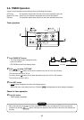
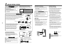
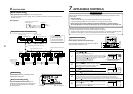
How to use the supplied installation pattern
The installation pattern is enclosed within the packaging of the air conditioner.
M5 × 16L screws (Attached)
These screws are exclusive to the
installation pattern. When installing
the ceiling panel, the other exclusive
screws attached to the ceiling panel
(sold separately) are used.)
Indoor unit
Installation pattern
(Attached)
Cut off the installation
pattern along slit of
the main unit.
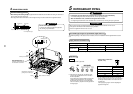
3
INSTALLATION OF INDOOR UNIT
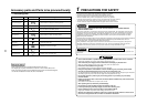
Hanging bolt
Nut
M10 or W3/8
M10 or W3/8
4 pieces
12 pieces
Existing ceiling void
Use the pattern to determine the position and size of the opening and
location of the hanging bolts.
New ceiling void
Use the pattern to determine the position of the new ceiling opening.
Cut off slit section of the main unit of the installation pattern.
Cut off the outside of the pattern according to size of the ceiling
opening. (There is a slit on the standard opening size section.)
• Install the indoor unit after installation of the hanging bolts.
• Using the supplied pattern attach it to the indoor unit using the
supplied fixing screws (M5 × 16L 4off). (Screw pattern to the ceiling
panel hanging brackets of the indoor unit)
• When creating the opening ensure it is as per the outer dimensions
of the supplied pattern.
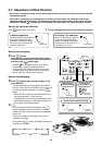
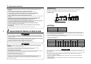
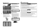
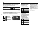
New concrete slab
Install the bolts with insert brackets or anchor
bolts.
Steel flame structure
Use existing angles or install new
support angles.
Existing concrete slab
Use a hole-in anchors, hole-in
plugs, or a hole-in bolts.
Anchor bolt
(Blade type
bracket)
(Slide type
bracket)
(Pipe hanging
anchor bolt)
Reinforcing
steel
Hanging bolt
Hanging bolt Support angle
Treatment of ceiling
The ceiling differs according to the structure of the building. For details, consult your architect.
In the process after the ceiling panels have been removed, it is important to reinforce the ceiling construction and
ensure the ceiling remains in a horizontal position. This is to prevent possible vibration of the ceiling panels.
1. Cut and remove the ceiling material.
2. Reinforce the cut surface of the ceiling construction and add support for fixing the end of ceiling panel.
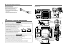
Installation of hanging bolt
Use M10 hanging bolts (4 off, locally procured).
When mounting the unit, set the pitch of the hanging bolts according to the size of the unit as detailed on the
dimensional drawing.
Hanging bolt
(W3/8 or M10)
Nut
(W3/8 or M10)
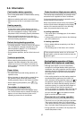
(1) M10 washer supplied, all other material
must be procured locally.
(2) To ensure that the unit is mounted safely, the
hanging bolt must be positioned just below
the hanging bracket as shown in the diagram.
(1)
M10 flat washer
(Accessory)
(2)
M10 flat washer
(Accessory)
Nut
(W3/8 or M10)
Installation gauge 2) 10 to 42 mm
1) 23 to 28 mm
Ceiling panel
Indoor unit
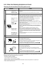
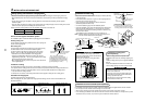
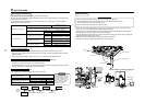
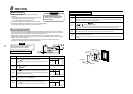
Installation of indoor unit
• Attach the nut (M10 or W3/8: Procured locally) and washer (Ø34 mm)
to the hanging bolt.
• Put washers at either side of the T-groove on the hanging bracket of
the indoor unit in order to hang the unit.
• Using a spirit level, check that all four sides are horizontal.
(Horizontal positioned within 5 mm)
• Cut off the installation gauge from the installation pattern.
• Using the installation gauge check and adjust clearance between the
indoor unit and the ceiling opening (1) (10 to 42 mm on each side).
Ensure that the unit is level to the ceiling and within a distance of (2)
23 mm to 28 mm below.
The installation gauge has details of how to use printed on it.
Note) Install the indoor unit so that the end part of opening does not
come into contact with the drain socket piping.
REQUIREMENT
Before installation of the indoor unit be sure to
remove the transportation cushion found between
the fan and the bell mouth.
Running the unit without removing the cushion
may damage the fan motor.
Indoor unit
Level vial (Horizontal: within 5 mm)
Hanging bolt
Hanging
metal
Installation gauge
Ceiling board
10 to 42
mm (2)
23 to 28 mm (1)
Installation of ceiling panel
(Sold separately)
Install the ceiling panel after completion of the
installation of the indoor unit, including all piping and
wiring.
Install the ceiling panel as per the supplied Installation
Manual.
Check the installation dimensions of the indoor unit
and the ceiling opening are correct and then install.
REQUIREMENT
Ensure the ceiling panel is mated to the ceiling
surface or the indoor unit.
If the panel and unit are not mated together this
may result in the formation of dew condensation
causing a possible water leak.
First remove the 4 corner caps from the ceiling
panel and fit to the indoor unit.
Be sure to remove the cushion for transportation
between the fan and the bell mouth.
Installation of remote controller (Sold separately)
For installation of the wired remote controller, follow the Installation Manual supplied with the remote controller.
• Do not expose remote controller to direct sunlight or excessive heat.
• When using a wireless type remote controller check receiver on the indoor unit receives a signal.
• For a wireless type controller ensure that it is used and mounted a minimum distance of 1m apart from any other
electrical devices (TV, Stereo, etc). As this may cause interference with the devices.