


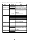

101
No.
5
Part name
Control P.C.
board
Procedure Remarks
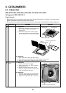
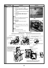
1. Detachment
1) Perform works of procedure
1
-1- and
2
-1.
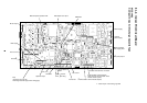
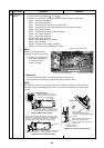
2) Remove the connectors connected from the control P.C. board to other parts.
CN33 : Flap motor (5P, White)
CN34 : Float switch (3P, Red)
CN41 : Terminal block of remote controller (3P, Blue)
CN40 : Terminal block of crossover between inside and outside (2P, Blue)
CN68 : Drain pump (3P, Blue)
CN67 : Terminal block of power supply (3P, Black)
CN100: TC1 sensor (3P, Brown)
CN101: TC2 sensor (2P, Black)
CN102: TCJ sensor (2P, Red)
CN104: Room temp sensor (2P, Yellow)
CN82 : PMV (6P, Blue)
CN333: Fan motor power supply (5P, White)
CN334: Fan motor position detection (5P, White)
NOTE)
Remove the connectors after
unlocking the lock of the housing.
3) Unlock the lock of the card
edge spacer (6 positions)
and then remove the
control P.C. board.
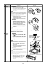
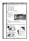
2. Attachment
1) Fix the control P.C. board to the card edge spacer. (6 positions)
2) Connect the connectors as original before being removed in item 1.
NOTE)
For drawing of each wire and position of ferrite core, perform wiring same as those before
removing. If there is incomplete drawing of wire, short or water leakage of the parts may be
caused.
Drawing-out port of lead wire
Card edge spacer
Card edge spacer
Card edge spacer
Ferrite core for fan motor
Ferrite core for sensor lead
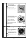
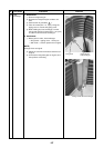
Details of fan motor lead wire drawing
Enlarged drawing
Fix the lead wires with cord clamp
so that the lead wires do not slacken
at P.C board side. (2 positions)
Cord clamp
Cord clamp
Cord clamp
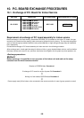
As shown in the figure, store PMV lead wire
connected with connector assembly so that the
connector positions under wire of the terminal.
Details of PMV lead wire drawing
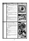
Details of sensor lead wire drawing
Fix the sensor lead wires firmly with the cord clamp so that
they do not touch with the caution plate of the terminal block
and they do not slacken at P.C. board side. (3 positions)
Arrange the clamp at the position as shown in the figure.
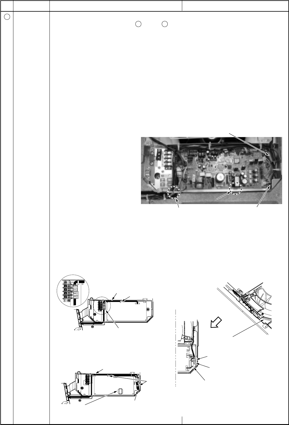
Fold back the sensor lead wire and
fix it surely with the cord clamp.
Adhere on the transformer.
Arrow view
Be sure that the
float switch lead wire positions
at inner side of the fan motor lead wire.
Fold back the float switch lead wire
and fix surely with cord clamp.
(There is no catching-in of P.C. board
and lead wire.)
Arrange at position
as shown in the figure.