


31
9
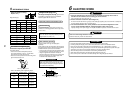
TROUBLESHOOTING
Confirmation and check
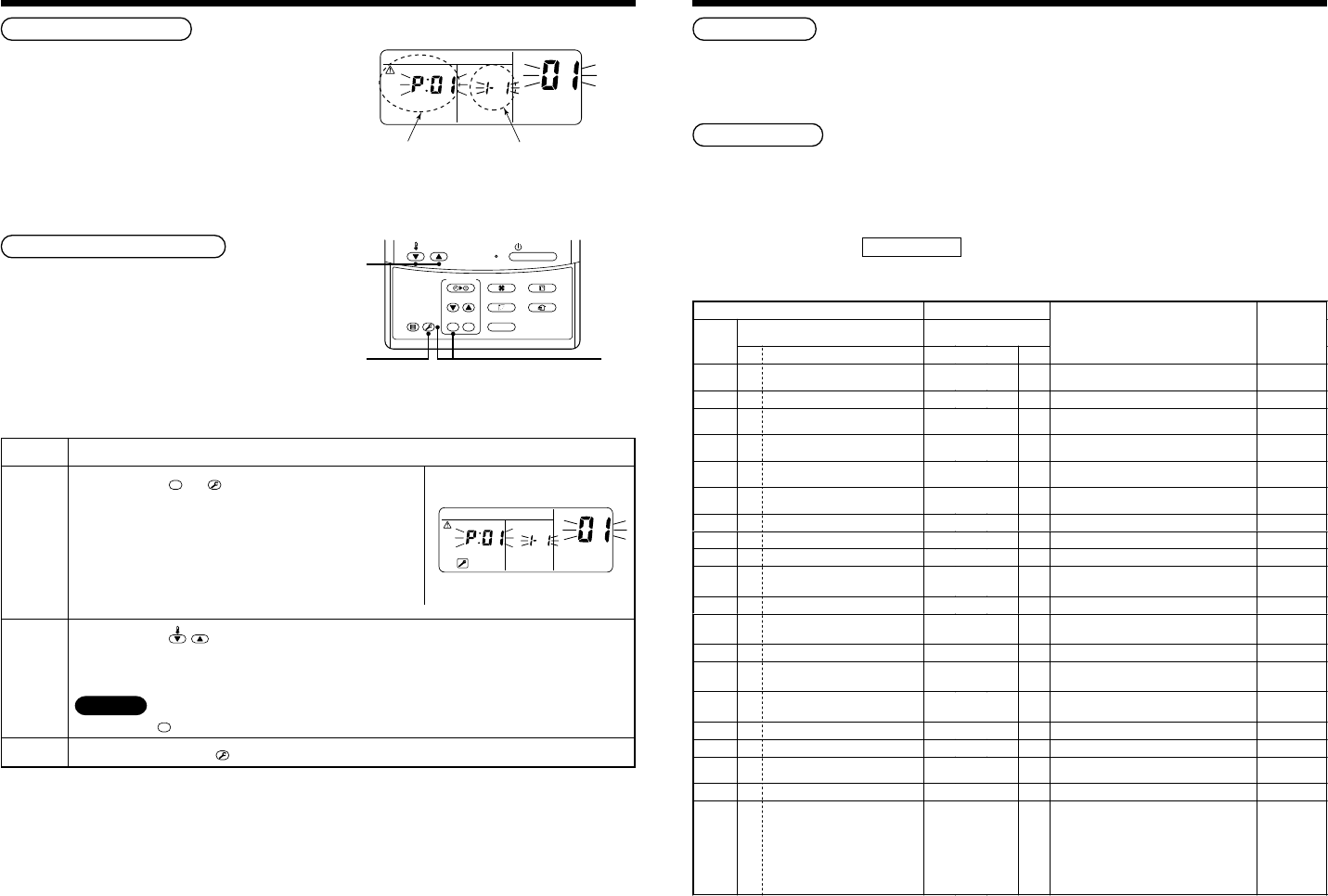
When a fault occurs in the air conditioner, the check
code and the indoor unit No. will appear on the display
part of the remote controller.
The check code will only be displayed while the unit is
in operation.
If the display disappears, operate the air conditioner
according to the following “Confirmation of error
history” for confirmation.
Confirmation of error history
When a fault occurs in the air conditioner, the error
history can be confirmed with the following procedure.
(The error history is stored in memory and can contain
up to 4 errors).
This history can be confirmed from either the operating
status or the stop status.
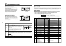
CODE No.
UNIT No.
R.C. No.
Check code Indoor unit No. in which
an error occurred
3
2
1
ON / OFF
FAN
TEMP.
SWING/FIXTIME
MODE
VENT
UNITSET CL
FILTER
RESET
TEST
TIMER SET
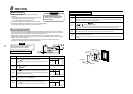
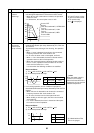
Procedure
1
2
3
Description
When pushing the
SET
and
TES
T
buttons simultaneously for 4 seconds
or more, the display similar to the one shown in the figure to the right
will appear.
If [Service Check] is displayed, the fault code will be stored in the
error history mode.
• 01 (Order of error history) is displayed in CODE No. window.
• Check Code is displayed in the CHECK window.
• The indoor unit address, where the fault has occurred will be
displayed in the UNIT No. window.
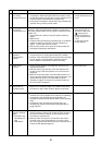
When pushing the
TEMP.
buttons, the error history stored within the memory will be displayed in
chronological order.
The numbers displayed within the CODE No. window can vary between 1 and 4. 1 being the most recent fault
and 4 being the oldest.
CAUTION
Do not push the
CL
button as this will erase all of the error history for that indoor unit.
After confirmation, push the
TES
T
button. This will return the display back to its original mode.
CODE No.
UNIT No.
R.C. No.
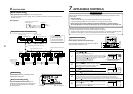
Check method
On the remote controller (Main remote controller, Central control remote controller) and the interface P.C. board of
the outdoor unit, a check display LCD (Remote controller) or 7-segment display (on the outdoor interface P.C.
board) operation is provided. Therefore the operation status can be known. Using this self-diagnosis function, a fault
and the location of this fault within the air conditioning system can be located, as shown in the table below.
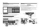
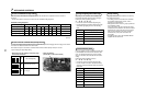
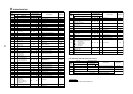
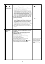
Check code list
The following list shows each check code. Find the check contents from the list according to part to be checked.
• In case of a fault from the indoor remote controller: See “Main remote controller display” in the list.
• In case of a fault from the outdoor unit: See “Outdoor 7-segment display” in the list.
• In case of a fault from the indoor unit with a wireless remote controller:
See “Sensor block display of receiving unit” in the list.
Terminology
IPDU : Intelligent Power Drive Unit
¡ : Lighting,
¤
: Flashing, l : Goes off
ALT. : Flashing is alternately when there are two flashing LED.
SIM : Simultaneous flashing when there are two flashing LED.
Check code Wireless remote controller
Outdoor 7-segment display
Sensor block display
of receiving unit
Main
remote
controller
display
Auxiliary code
Operation
Timer Ready Flash
Check code name Judging device
E01 ——
¤
ll
Communication error between indoor and remote
controller (Detected at remote controller side)
Remote controller
E02 ——
¤
ll
Remote controller transmission error Remote controller
E03 ——
¤
ll
Communication error between indoor and remote
controller (Detected at indoor side)
Indoor
E04 ——
ll
¤
Communication circuit error between indoor/outdoor
(Detected at indoor side)
Indoor
E06 E06
No. of indoor units in which sensor has
been normally received
ll
¤
Decrease of No. of indoor units I/F
— E07 —
ll
¤
Communication circuit error between indoor/outdoor
(Detected at outdoor side)
I/F
E08 E08 Duplicated indoor addresses
¤
ll
Duplicated indoor addresses Indoor / I/F
E09 ——
¤
ll
Duplicated main remote controllers Remote controller
E10 ——
¤
ll
Communication error between indoor MCU Indoor
E12 E12
01: Indoor/Outdoor communication
02: Communication between outdoor units
¤
ll
Automatic address start error I/F
E15 E15 —
ll
¤
Indoor is nothing during automatic addressing I/F
E16 E16
00: Capacity over
01 ~: No. of connected units
ll
¤
Capacity over / No. of connected indoor units I/F
E18 ——
¤
ll
Communication error between indoor units Indoor
E19 E19
00: Header is nothing
02: Two or more header units
ll
¤
Outdoor header units quantity error I/F
E20 E20
01: Outdoor of other line connected
02:Indoor of other line connected
ll
¤
Other line connected during automatic address I/F
E23 E23 —
ll
¤
Sending error in communication between outdoor units I/F
E25 E25 —
ll
¤
Duplicated follower outdoor addresses I/F
E26 E26
No. of outdoor units which received signal
normally
ll
¤
Decrease of No. of connected outdoor units I/F
E28 E28 Detected outdoor unit number
ll
¤
Follower outdoor unit error I/F
E31 E31
01: IPDU1 error
02: IPDU2 error
03: IPDU1, 2 error
04: Fan IPDU error
05: IPDU + Fan IPDU error
06: IPDU2 + Fan IPDU error
07: All IPDU error
ll
¤
IPDU communication error I/F