


76
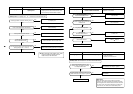
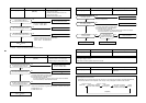
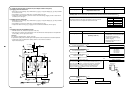
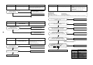
(*3) Check for solenoid valve of outdoor unit (For multiple outdoor unit system)
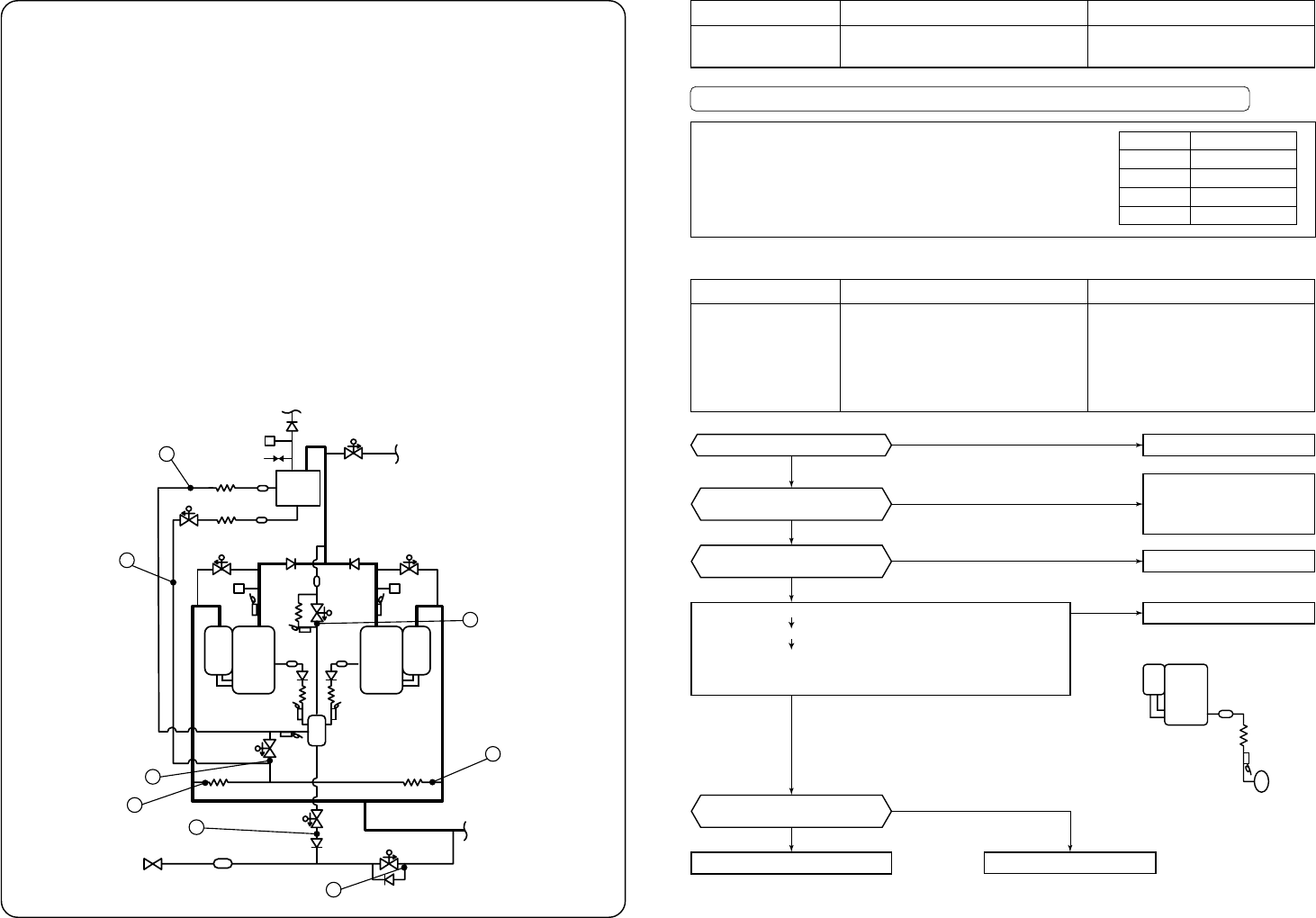
a) Clogging check for SV3A valve
• While outdoor unit is operating, set up SW01/02/03 = [2] [1] [3] to 7-segment display [Hr] [ 2], and push SW04
for 2 seconds or more.
• Set up SW02 = [4], and turn on SV3A valve. (7-segment display [Hr] [ 3A])
• If temperature is low at secondary side of the valve or it does not change, clogging of valve or check valve is
considered. (
in the figure.)
b) Leakage check for SV3C valve
• While outdoor unit is operating, set up SW01/02/03 = [2] [1] [3] to 7-segment display [Hr] [ 2], and push SW04
for 2 seconds or more.
• Set up SW02 = [6], and turn on SV3C valve. (7-segment display [Hr] [ 3C])
• If temperature does not change (up), clogging of valve or strainer is considered. (
in the figure.)
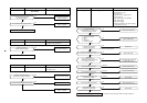
(*4)
a) Clogging check for oil-equalization circuit
• Drive the outdoor unit. (Drive both compressors in the unit.)
• After driving for 10 minutes, check temperature of TK1 and TK2 sensors and temperature of oil-equalization
circuit capillary (
in the figure) were raised.
(Criterion)
TK1, TK2=Td1, Td2 temperature – Approx. 10 to 30°C
Oil-equalization capillary tubes should be higher sufficiently than outside air temperature and suction temperature.
• If temperature is low, a malfunction of capillary, strainer, or check valve is considered.
Repair the defective parts.
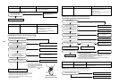
(SV2)
Solenoid valve
(SV41)
(SV3D)
Check joint
High-pressure
sensor
High-pressure
SW
Oil
separator
Compressor 1
(Inverter)
Strainer Strainer
Sensor
(TK3)
(TK1)
(SV3E)
(TK4)
(TK2)
Solenoid valve
(SV42)
High-pressure
SW
Compressor 2
(Inverter)
Sensor
(TD2)
(TD1)
Oil tank
(SV3A)
Solenoid
valve
(SV3B)
Check
valve
Strainer
5
6
4
7
3
1
7
2
Balance pipe
Packed valve
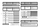
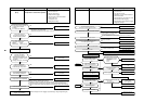
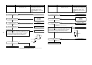
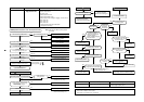
Check code name
[H08]
Check code name
Oil level detective
temperature sensor error
Cause of operation
TK1 to TK4 sensor Open/Short
Auxiliary code : 01: TK1 sensor error 02: TK2 sensor error 03: TK3 sensor error 04: TK4 sensor error
Circuit
TK1
TK2
TK3
TK4
Connector
CN514 (Black)
CN515 (Green)
CN516 (Red)
CN523 (Yellow)
The detected error is an oil level detective temperature sensor error.
Check disconnection of the wiring and resistance value of the sensor.
If the sensors are normal, replace the outdoor I/F P.C. board.
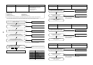
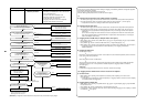
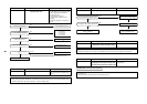
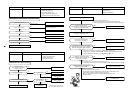
Check code name
[H16]
Check code name
TK1 temperature detective circuit error
(Auxiliary code : 01)
Cause of operation
1. Coming-off of TK1 sensor, miscabling,
characteristics error of resistance value
2. Oil-equalization circuit error
(Check valve, capillary clogging,
strainer clogging)
3. Refrigerant stagnation in case of
compressor shell
Is not TK1 sensor detached?
Is there no miscabling or misinstallation
on TK1/TK2/TK3/TK4 sensors?
Start a test operation in COOL or HEAT mode.
TK1 sensor temp is displayed on 7-segment display with SW01/02/03=[1] [11] [2].
Check TK1 sensor temp approx. 10 minutes after compressor 1 has operated.
If low temperature continues (approximately outside temp) or temperature
does not almost change, a clogging of strainer of oil-equalization circuit,
clogging of capillary tube, or malfunction of check valve is considered.
(Note 1) Refer to item [H07] error.
* Outdoor unit temp sensor characteristics-4
* Characteristics-4
Correct miscabling/misinstallation.
TK1: CN514
TK2: CN515
TK3: CN516
TK4: CN523
( )
YES
YES
YES
NO
NO
NO
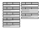
Check I/F P.C. board
Correct installation of sensor.
Are characteristics of TK1 sensor
resistance value normal?
Check the clogging of SV3E valve.
(Note 1)
No error
Error
Error
No error
Sensor error
Replace clogged part.
Replace SV3E valve.
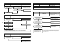
Strainer
Compressor 1
Oil tank
Capillary tube
TK1