


27
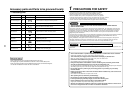
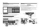
Power supply specifications
Power supply wiring and communication wiring are to be procured locally.
For the power supply specification, follow the table below. Ensure power supply is adequate. An insufficient power
supply could result in unit failure.
For specification of the power capacity of the outdoor unit and the power supply wires, refer to the Installation
Manual supplied with the outdoor unit.
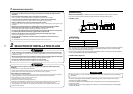
Indoor unit power supply (*1)
• Indoor unit power supply, must have a dedicated supply and be separate to that of the outdoor unit.
• Arrange the power supplies to the indoor and outdoor units, so that a common earth leakage breaker and main
switch can be used.
• Power supply cable specification : Cable 3-core 2.5 mm², in conformity with Design 60245 IEC 57.
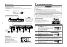
Indoor/Outdoor inter-unit wiring, Central controller wiring (*2) (*3)
• Use a 2 core non polarity cable.
• To prevent any possible noise issues, use a shielded 2 core wire.
• The total stated length of communication wiring is determined by the interconnecting length of indoor to outdoor
cable plus the length of the central control communication cable.
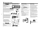
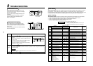
Remote controller wiring (*4)
• For wiring remote controllers, a 2 core polarity cable must be used.
Remote controller inter-unit wiring
Indoor unit
Remote
controller
Indoor unit
L1 L2 Ln
(Max. 8 units)
Indoor unit Indoor unit
Remote
controller
wiring
CAUTION
The remote controller wire
(Communication line) and AC220–
240V (Power supply) wires cannot
be parallel to contact each other
and cannot be stored in the same
conduits. If doing so, a trouble
may be caused on the control
system due to noise, etc.
6
ELECTRIC WORK
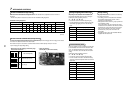
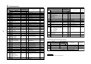
Indoor unit power supply (*1)
Communication line
Power supply
220–240V, 1N ~ 50Hz
220V, 1N ~ 60Hz
Power supply switch/Earth leakage breaker or power supply wiring/fuse rating for indoor
units should be selected by the accommodated total current values of the indoor units.
Power supply wiring
20 m or less Twist wire : 2.5 mm²
50 m or less Twist wire : 3.5 mm²
Q’ty 2
Indoor/Outdoor inter-unit wiring (*2)
Wire size
(Up to 1000 m) Twist wire : 1.25 mm²
(Up to 2000 m) Twist wire : 2.00 mm²
Q’ty 2
Central control line wiring (*3)
Wire size
(Up to 1000 m) Twist wire : 1.25 mm²
(Up to 2000 m) Twist wire : 2.00 mm²
Remote controller wiring (*4)
Q’ty 2
Wire size Twist wire : 0.5 to 2.0 mm²
Twist wire: 0.5mm
2
to 2.0 mm
2
× 2
Total wire length of remote controller
wiring and remote controller inter-unit
wiring = L + L1 + L2 + … Ln
In case of wired type only
In case of wireless type included
Remote controller wiring, remote
controller inter-unit wiring
Total wire length of remote controller inter-unit wiring = L1 + L2 + … Ln
Up to 500 m
Up to 400 m
Up to 200 m
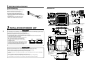
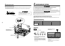
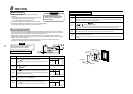
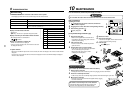
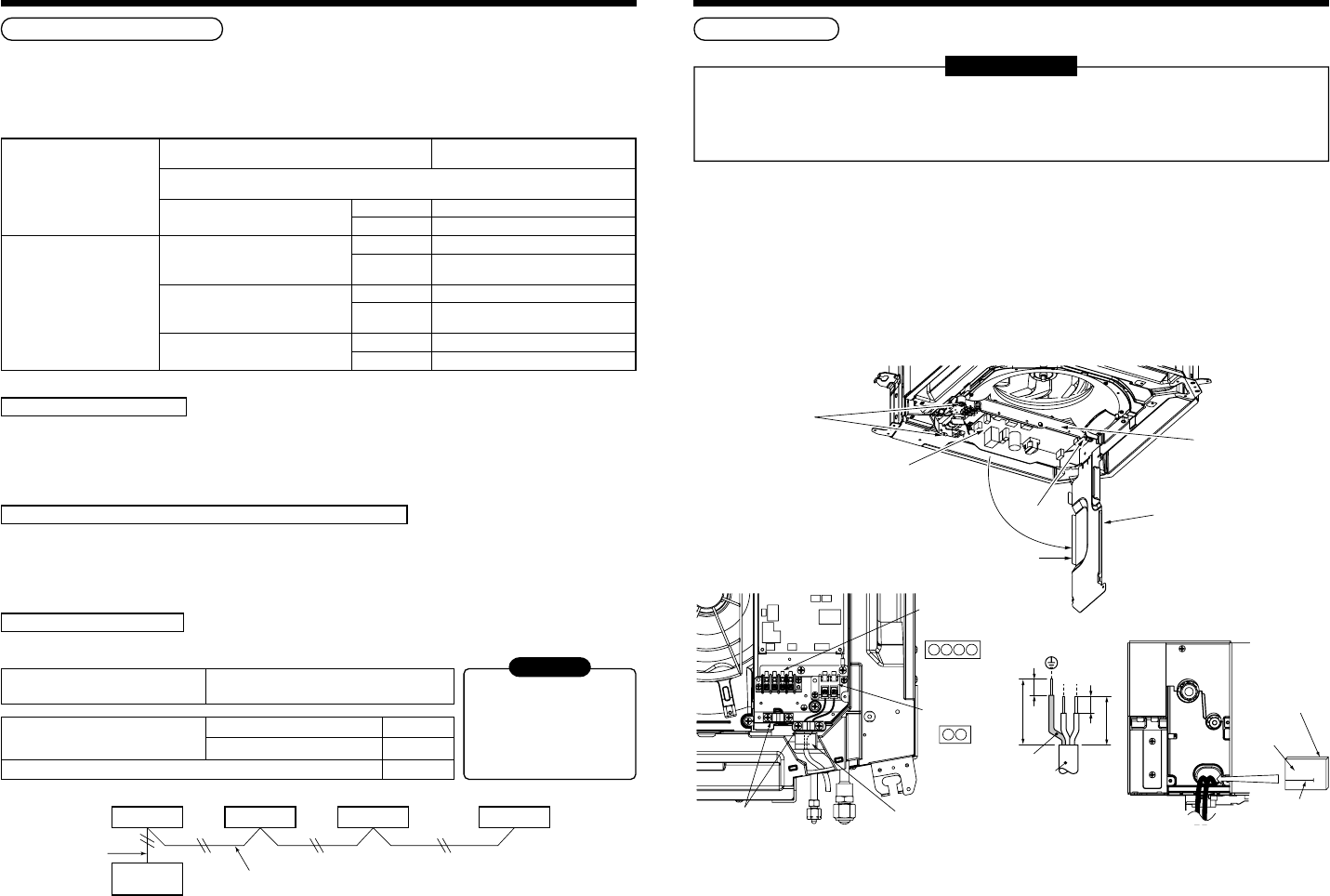
Cable connection
REQUIREMENT
• Be sure to locate the cable through the cable connection port of the indoor unit.
• Ensure additional wire length of approximately 100 mm at the indoor unit electric parts box.
This is to enable ease of any service work in the future.
• The low-voltage circuit is provided for the remote controller.
• Remove the cover of the electric parts box by removing the mounting screws (3 pcs.) and push the hooking
section. (The cover of the electric parts box remains hanged to the hinge.)
• Tighten the screws on the terminal block and secure the cables with cord clamp fitted to the electric parts box.
(Do not apply tension to the connecting section of the terminal block.)
• Using the supplied thermal insulation for the sealing of the cable connecting port, seal the cable connecting port.
(Otherwise dew condensation may be caused.)
• Mount the cover of the electric parts box ensuring the cables are not pinched.
(Mount the cover after the ceiling panel has been wired to the electric box.)
P.C. board
Cover of electric parts box
Hooking section
Screw
Screws
Electric parts box
Thermal insulation to cabling connecting port
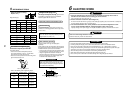
R
(L)
S
(N)
10
10
50
70
Earth line
Connecting
cord
R(L)S(N)
Cord clamp Heat insulator B
Heat insulator A
Indoor/Outdoor
crossover cable/
Remote controller
terminal block
Power supply
terminal block
U
1
U
2
A B
Adhered surface
Notched section