


34
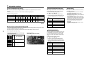
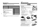
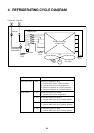
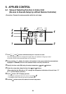
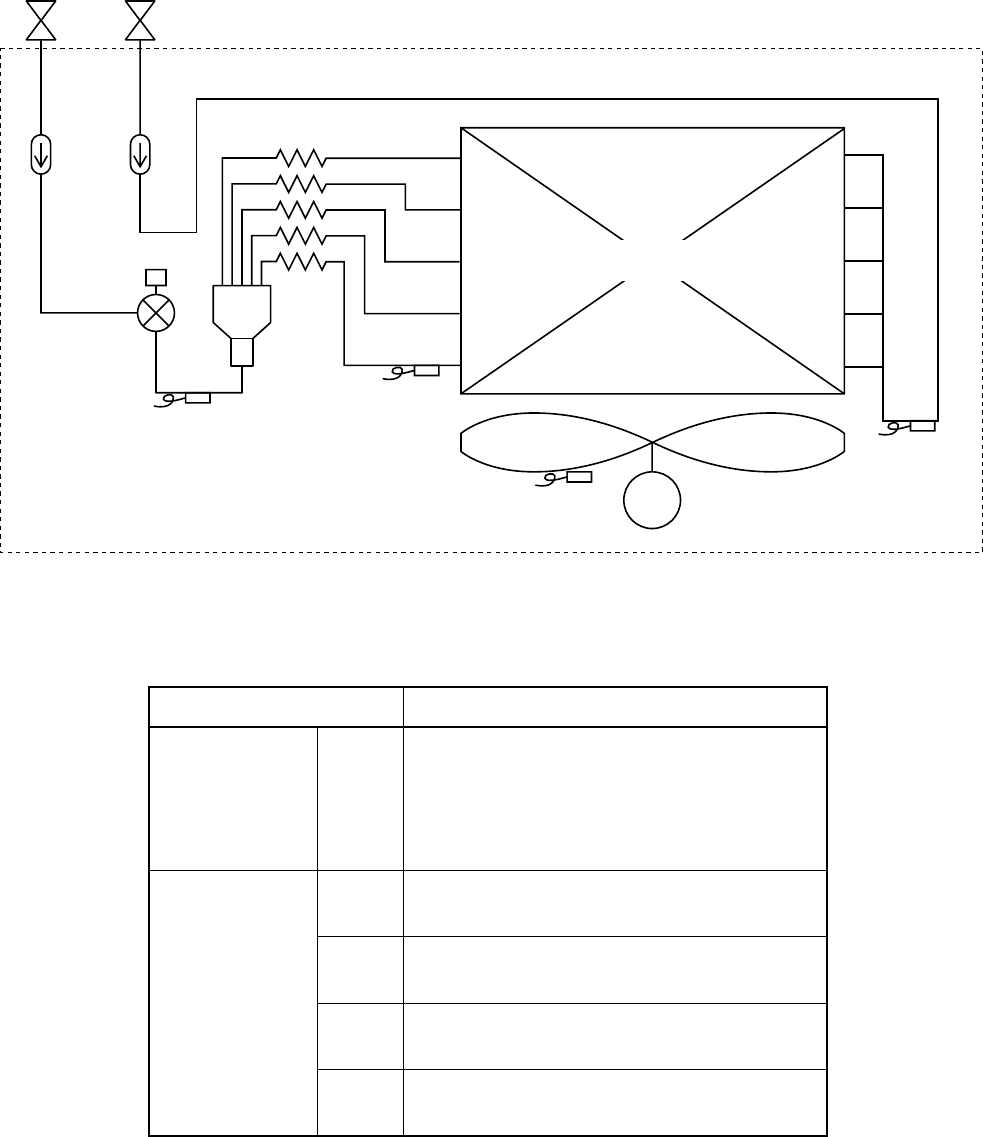
4. REFRIGERATING CYCLE DIAGRAM
Air heat exchanger
at indoor side
Fan
M
Fan motor
Sensor
(TA)
Sensor
(TC1)
Gas sideLiquid side
Strainer
Capillary tube
Pulse Motor
Valve (PMV)
Strainer
Sensor
(TCJ)
Sensor
(TC2)
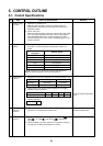
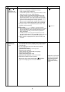
Functional part name
Pulse Motor Valve PMV
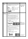
Temp. sensor 1. TA
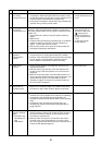
2. TC1
3. TC2
4. TCJ
Functional outline
(Connector CN082 (6P): Blue)
1) Controls super heat in cooling operation
2) Controls under cool in heating operation
3) Recovers refrigerant oil in cooling operation
4) Recovers refrigerant oil in heating operation
(Connector CN104 (2P): Yellow)
1) Detects indoor suction temperature
(Connector CN100 (3P): Brown)
1) Controls PMV super heat in cooling operation
(Connector CN101 (2P): Black)
1) Controls PMV under cool in heating operation
(Connector CN102 (2P): Red)
1) Controls PMV super heat in cooling operation