


29
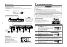
In case of installation to high ceiling
When the unit is to be installed at a height that exceeds the standard value, adjustment to the air volume is
necessary.
• For the “Setup data” in Procedure
2
, select from the “Installable ceiling height list”.
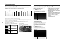
Installable ceiling height list
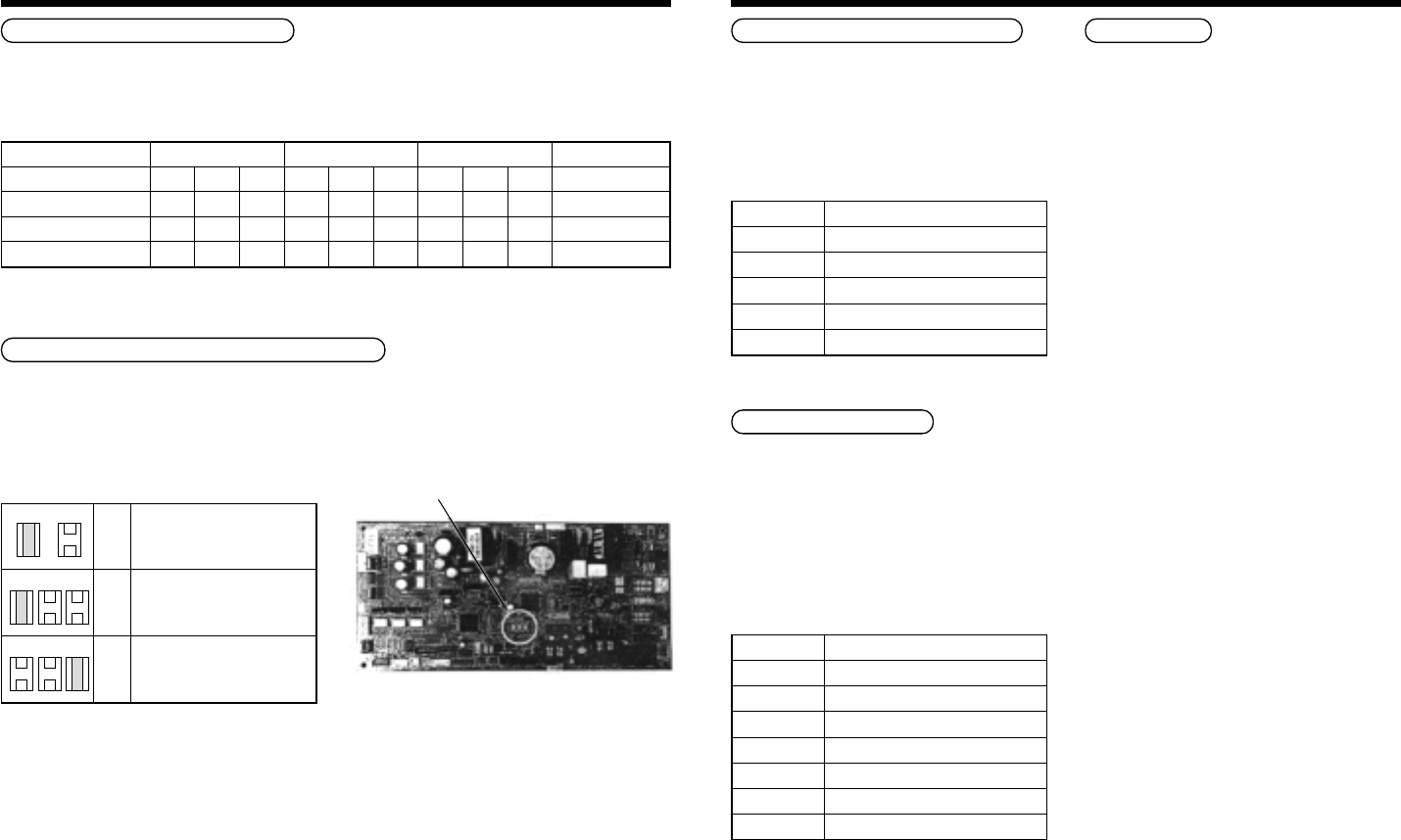
• Select setting by the changing of the short plugs
on the indoor P.C. board.
• Short plug position
(CN112, CN111, CN110 from the left)
7
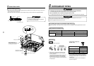
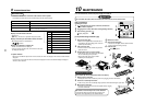
APPLICABLE CONTROLS
Short plug position
Set
data
0000
0003
Filter sold separately
Standard filter (At shipment)
High ceiling (3)
Short
CN112 CN111 CN110
Open
CN112 CN111 CN110
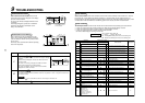
In case of remote controller-less (Group control)
To set the unit to high ceiling operation, there is a method that requires the changing of the short plugs on the indoor
P.C. board. The details are shown in the below table.
This method is only to be used where a standard wired remote controller (Group control) is not used.
∗ Upon changing the high ceiling setting
Indoor unit capacity type
Discharge direction
Standard (At shipment)
High ceiling (2)
High ceiling (3)
0071 to 0121 type 0151 type 0181 type
4-way 3-way 2-way 4-way 3-way 2-way 4-way 3-way 2-way
2.7 ——2.9 ——3.2 ——
———3.2 ——3.4 ——
———3.5 ——3.5 ——
Setup of high ceiling
Setup data
0000
0002
0003
(Unit: m)
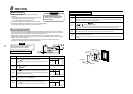
Change of lighting time of filter sign
Depending on the conditions of the installation, the
time period of the filter clean sign can be changed.
Follow to the basic operation procedure
(
1
→
2
→
3
→
4
→
5
→
6
).
• For the item code in Procedure
3
, specify [01].
• For the [Set data] in Procedure
4
, select the setup
data of filter sign lighting time from the following
table.
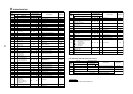
Increased heating effect
If it is not possible to achieve satisfactory heating due
to the installation environment or the structure of the
room. The detected temperature can be increased.
Also use a circulator, etc to circulate hot air near the
ceiling.
Follow to the basic operation procedure
(
1
→
2
→
3
→
4
→
5
→
6
).
• For the item code in Procedure
3
, specify [06].
• For the set data in Procedure
4
, select the setup
data of the required temperature shift value from the
table below.
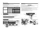
Group control
In a group control, a remote controller can control up
to a maximum of 8 units.
• For cabling procedure and cables of the individual
line (Identical refrigerant line) system, refer to
“Electric work” in this Manual.
• Wiring between indoor units in a group is performed
in the following method.
Connect the indoor units by connecting the remote
controller inter-unit cables from the remote controller
terminal blocks (A, B) of the indoor unit connected
with a remote controller to the remote controller
terminal blocks (A, B) of the other indoor unit.
(No polarity)
• For address setup, refer to the Installation Manual
supplied with the outdoor unit.
Setup data
0000
0001
0002
0003
0004
0005
0006
Detection temp shift value
No shift
+1°C
+2°C (At shipment from factory)
+3°C
+4°C
+5°C
+6°C
Setup data
0000
0001
0002
0003
0004
Filter sign lighting time
None
150H
2500H (At shipment from factory)
5000H
10000H