


65
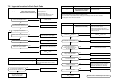
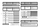
7-5. Diagnosis Procedure for Each Check Code
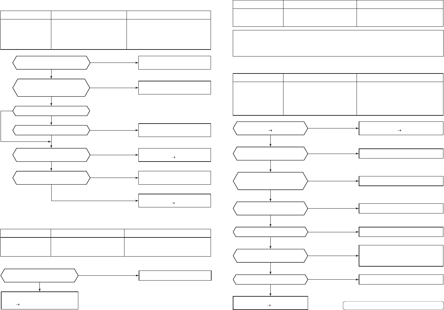
Check code
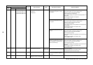
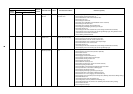
[E01]
Check code name
Communication error between
indoor and remote controller
(Detected at remote controller side)
Cause of operation
1. Remote controller inter-unit cable error
2. Indoor power error
3. Indoor P.C. board error
4. Remote controller address setup error
5. Remote controller P.C. board error
Is a group control operation?
Is power of each indoor unit turned on?
YES
YES
YES
YES
YES
YES
NO
NO
NO
NO
NO
NO
Is there no disconnection or
connector contact error on harness out
of terminal block of indoor unit?
Is the inter-unit cable of
remote controllers (A/B) normal?
Is power applied to remote controller?
AB terminals: Approx. DC18V
Is setup of two remote controllers
without main remote controller?
Correct inter-unit cable of
remote controller.
Correct connector connection
and check circuit cabling.
Check power connection status of
indoor unit. (Turn on power again.)
Check indoor P.C. board.
Defect Replace
Change one to main/other to sub.
(Remote controller address connector)
Check remote controller P.C. board.
Defect Replace
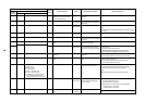
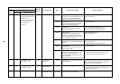
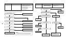
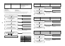
Check code name
Remote controller sending error
Cause of operation
Signal could not be sent to indoor unit.
Check the communication wire of the remote
controller.
* It is not displayed on 7-segment display of the central control controller.
Check code
[E02]
YES
NO
Is communication cabling between
remote controller and indoor unit correct?
Sending circuit error
inside of the remote controller
Replace remote controller.
Correct the communication cabling.
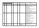
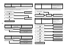
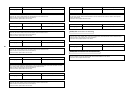
Check code
[E03]
Check code name
Communication error between
indoor and remote controller
(Detected at indoor side)
Cause of operation
No communication from remote controller and
communication adaptor
This error is detected when the indoor unit cannot receive a signal from the remote controller.
Check communication wires of the remote controllers A and B.
As communication is impossible, this check code [E03] is not displayed on the main remote controller.
It is displayed on TCC-LINK central controller.
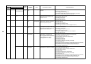
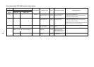
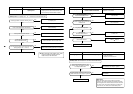
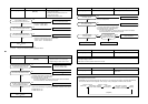
Check code
[E04]
Check code name
Indoor/Outdoor
communication circuit error
(Detected at indoor side)
Cause of operation
1. Power of outdoor unit was firstly turned on.
2. Connection error of communication line
between indoor and outdoor
3. End terminal resistance setup error on
communication between indoor and outdoor
4. Address setup error
For details, refer to “Troubleshooting in test operation”.
Is address setup correct?
Is there no noise, etc?
YES
YES
YES
YES
YES
YES
YES
NO
NO
NO
NO
NO
NO
NO
Is connector connection from
U1/U2 terminals of indoor/outdoor
inter-unit wire normal?
Was power turned on in order
of indoor unit outdoor unit?
Is the end terminal resistance
setup of outdoor unit normal?
Is power applied to fuse (F03)
on indoor P.C. board?
Is connection (U1/U2 terminals) of
indoor/outdoor inter-unit wire normal?
Check indoor P.C. board.
Defect Replace
Check connection of inter-unit wire between
indoor and outdoor is correct, and then
connect communication line connector on
indoor P.C. board (CN40) to CN44 (EMG).
Correct inter-unit wire.
Turn on power again in order of
indoor unit
outdoor unit.
Correct connector connection.
Correct the end terminal resistance setup.
Set up address again.
Check noise, etc, and eliminate it if any.