


11
1
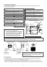
SET DATA display
Displayed during setup of the timer.
2
Operation mode select display
The selected operation mode is displayed.
3
CHECK display
Displayed while the protective device works or a
trouble occurs.
4
Timer time display
Time of the timer is displayed. (When a trouble
occurs, the check code is displayed.)
5
Timer SETIN setup display
When pushing the Timer SET button, the display
of the timer is selected in order of
[OFF]
→ [OFF] repeat OFF timer
→ [ON]
→ No display.
6
Filter display
If “FILTER ” is displayed, clean the air filter.
7
TEST run display
Displayed during a test run.
8
Flap position display
Displays flap position.
9
SWING display
Displayed during up/down movement of the flap.
10
Set up temperature display
The selected set up temp. is displayed.
11
Remote controller sensor display
Displayed while the sensor of the remote
controller is used.
12
PRE-HEAT display
Displayed when the heating operation starts.
While this indication is displayed, the indoor fan
stops.
13
Operation ready display
Displayed when cooling or heating operation is
impossible because the outdoor temperature goes
out of the operable range.
14
No function display
Displayed if there is no function even if the button is
pushed.
15
Air volume select display
The selected air volume mode is displayed.
(AUTO)
(HIGH)
(MED.) (LOW)
16
Mode select control display
Displayed when pushing “Operation mode select ”
button while the operation mode is fixed to heating
or cooling by the system manager of the air condi-
tioner.
17
Central control display
Displayed when using the remote controller together
with the central control remote controller, etc.
If Remote controller is prohibited at the
centralcontrol side,
flashes when operating
ON / OFF
,
MODE
, / buttons and
the change is not accepted.
(The contents available to be set up on the remote
controller differ according to the central control
mode. For details, refer to Owner’s Manual of the
central control remote controller.)
Display
section
Operation
section
ON / OFF
FAN
TEMP.
SWING/FIXTIME
MODE
VENT
UNITSET CL
FILTER
RESET
TEST
TIMER SET
CODE No.
UNIT No.
TEST
SETTING
DATA
SET
R.C. No.
H
2
15
5
78 9
3
1
4
6
10
11
13
16
12
14
17
CODE No.
UNIT No.
TEST
SETTING
DATA
SET
R.C. No.
H
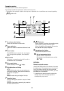
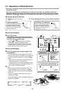
3-3. Parts Name of Remote Controller
Display section
In the display example, all indicators are displayed for the explanation.
In reality only, the selected contents are indicated.
• When turning on the leak breaker at the first time, [SET DATA] flashes on the
display part of the remote controller. While this display is flashing, the model is
being automatically confirmed. Accordingly, wait for a while after [SET DATA]
display has disappeared, and then use the remote controller.