


28
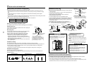
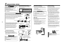
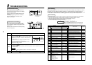
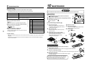
Remote controller wiring
• Strip approximately 14 mm of insulation off of the connecting wires.
• As the remote controller wire has no polarity, there is no problem if connections to indoor unit terminal blocks A
and B are reversed.
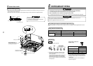
Wiring diagram
Wiring between indoor and outdoor units
NOTE
An outdoor unit that is
inter-connected to the
indoor units automatically
becomes the header unit.
Terminal block for remote controller
wiring of indoor unit
A
B
A
B
Remote controller wire (Field supply)
Terminal block
Remote
controller unit
Address setup
Set up the addresses as per the Installation Manual
supplied with the outdoor unit.
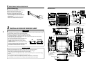
Wiring on the ceiling panel
As per the Installation Manual of the ceiling panel,
connect the connector (2P: Red) of the ceiling panel to
the connector (5P: White) onto the P.C. board within
the electric parts box.
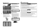
6
ELECTRIC WORK
Connection of shield wire closed terminal
Control wiring between indoor and outdoor units
Control wiring between outdoor units
Outdoor power supply
Control wiring between indoor units
U2U1 A B
BA
Indoor unit
Earth
Remote
controller
Pull box
Earth leakage
breaker
Power switch
Indoor power supply
220-240V, 1N ~50Hz
220V, 1N ~60Hz
LN
U1U2U3U4U5U6
Header outdoor unit
Earth
Outdoor power supply
U2U1 A B
BA
Indoor unit
Earth
Remote
controller
Pull box
LN U2U1 A B
BA
Indoor unit
Earth
Remote controller
[Group control]
Pull box
LN U2U1 A B
Indoor unit
Earth
LN
U1U2U3U4U5U6
Follower outdoor unit
Earth
Cord Clamp
5P connector (White)
Wire from ceiling panel
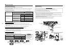
7
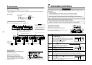
APPLICABLE CONTROLS
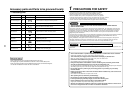
NOTIFICATION
When using the equipment for the first time, the remote controller will not accept any commands for a short
period of time.
• Automatic address
• While automatic addressing no operations can be performed on the remote controller.
• Automatic addressing will take a maximum duration of 10 minutes (generally 5 minutes).
• Upon turning on the unit after completion of automatic addressing, a maximum period of
10 minutes (generally 3 minutes) are required prior to the start up operation of the outdoor unit.
All indoor units are shipped from factory as standard. Change if necessary.
To change the setup use the main remote controller (wired remote controller).
* The setup change for wireless remote controller, sub remote controller or a unit without a controller (Centrally
controlled.) is not possible. In such cases, temporarily install a separate main remote controller.
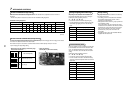
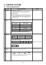
Applicable control setup
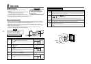
Basic operation procedure for setup change
Change the setup while operation of the equipment is stopped.
(Be sure to stop the operation of a set.)
ON / OFF
FAN
TEMP.
SWING/FIXTIME
MODE
VENT
UNITSET CL
FILTER
RESET
TEST
TIMER SET
CODE No.
UNIT No.
R.C. No.
1
2
3
5
6
6
Procedure
1
2
3
4
5
6
Description
Push the
SET
,
CL
and
TES
T
buttons simultaneously for 4 seconds or more, after a while, the display part flashes
as shown in the figure.
Check that the displayed item code is [10].
• If the item code indicates any characters other than [10], push the
TES
T
button to erase the display and retry the operation from the first step.
(For some time after the
TES
T
button has been pushed, the operation
of the remote controller cannot be accepted.)
(In a group control, the firstly displayed
indoor unit No. becomes the center unit.)
Each time the
UNIT
button is pushed, the indoor unit No. in the group control is displayed consecutively.
Select the indoor unit that requires a change to the setup.
During this time the indoor unit that is selected can be
confirmed as the louver and fan will be operated.
Using
TEMP.
the buttons, select the item code [
**
].
Using the
TIME
buttons, select set data [
****
].
Push the
SET
button. During this time, if the display changes from flashing to permanently on, the setup is
complete.
• To change the setup of an indoor unit that is not selected, restart operation from Procedure
2
.
• To change to a different setup within the selected indoor unit, restart operation from Procedure
3
.
Pushing the
CL
button clears the set up contents which has been set. In this case, restart from Procedure
2
.
When the setup is finished, push the
TES
T
button. (The setup is configured.)
Pushing the
TES
T
button deletes the display and returns the status to the
normal stopped status.
(For a period of time after the
TES
T
button has been pushed, the remote
controller will not accept any commands.)
(* The display changes according
to the indoor unit model.)
CODE No.
UNIT No.
R.C. No.
∗
∗∗
∗∗
∗
∗
∗
∗∗∗
CODE No.
UNIT No.
SETTING
R.C. No.