


106
No.
13
Part name
PMV
(Pulse Motor Valve)
Procedure
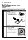
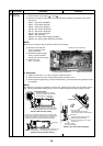
1. Detachment
1) Perform work of procedure
11
-1.
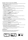
2) Take off screws (Ø4 × 10, 3 pcs.) fixing
the piping cover to remove the piping
cover.
3) Cut off binding band that binds the PMV
lead wires.
4) Peel butyl rubber of PMV a little and
remove PMV motor with a spanner
wrench.
NOTE)
For attachment and detachment of PMV motor,
use a 14mm or 19mm spanner wrench.
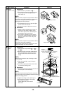
2. Attachment
1) Mount PMV motor with a spanner
wrench.
NOTE)
PMV motor tightening torque: 7.84 ± 0.78N.m
2) Perform wiring of PMV and sensor lead
as original.
NOTE)
Arrange each wire as original.
3) Fix the piping cover with screws.
Remarks
3 screws
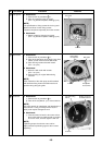
PMV body
PMV body
PMV nut
PMV nut
Piping cover
Piping cover
PMV body PMV nut
Piping cover
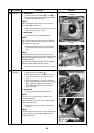
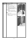
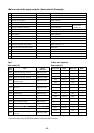
As shown in the figure, hook the
sensor and PMV lead wires to the
claw of the No.13 piping cover,
and then pass them so that they
are stored in this groove.
When mounting the piping cover,
check each lead wire
does not hit PMV motor.
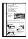
<Details of sensor lead wire drawing>
As shown in the figure, make draining shape on the
lead wire (Black) once, and then fix it with bind band.
Sensor lead wire (Black)
Do not turn the head
of bind band upward.
Sensor lead wire
(Red)
Sensor lead wire (Blue)
(Inner
sparkle side)
Bind band
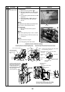
Arrow view B
A
B
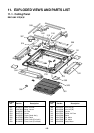
Bundle each sensor lead wire (Red), (Blue), (Black),
and PMV lead wire, fold back toward you at position
in the figure, and then fix them with bind band.
Sensor lead wires
(Red) (Blue)
Sensor lead wire (Black)
PMV lead wire
(PMV lead
from foot)
(20)
(70)
(80)
Heat-insulation pipe
(Liquid pipe)
Sensor lead
(Red)
Sensor lead
(Blue)
Heat-insulation pipe
(Gas pipe)
Insert the sensor lead wires (Red), (Blue), (Black)
from the positions in the figure.
Sensor lead (Black)
PMV motor
Fix the head of bind band and lead wire at inner side of the
position in the figure so that they do not stick out to outside.
Details of A part
(70)
(80)