


User's Guide
SPRUEN0D–March 2011
Inter-Integrated Circuit (I2C) Peripheral
1 Introduction
This document describes the operation of the inter-integrated circuit (I2C) peripheral in the TMS320C642x
Digital Signal Processor (DSP). The scope of this document assumes that you are familiar with the Philips
Semiconductors Inter-IC bus (I2C-bus) specification version 2.1.
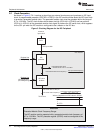
1.1 Purpose of the Peripheral
The I2C peripheral provides an interface between the TMS320C642x DSP and other devices that are
compliant with the I2C-bus specification and connected by way of an I2C-bus. External components that
are attached to this two-wire serial bus can transmit and receive data that is up to eight bits wide both to
and from the DSP through the I2C peripheral.
1.2 Features
The I2C peripheral has the following features:
• Compliance with the Philips Semiconductors I2C-bus specification (version 2.1):
– Support for byte format transfer
– 7-bit and 10-bit addressing modes
– General call
– START byte mode
– Support for multiple master-transmitters and slave-receivers mode
– Support for multiple slave-transmitters and master-receivers mode
– Combined master transmit/receive and receive/transmit mode
– I2C data transfer rate of from 10 kbps up to 400 kbps (Philips I2C rate)
• 2 to 8 bit format transfer
• Free data format mode
• One read DMA event and one write DMA event that the DMA can use
• Seven interrupts that the CPU can use
• Peripheral enable/disable capability
1.2.1 Features Not Supported
• High-speed mode
• CBUS-compatibility mode
• The combined format in 10-bit addressing mode (the I2C sends the slave address the second byte
every time it sends the slave address the first byte).
7
SPRUEN0D–March 2011 Inter-Integrated Circuit (I2C) Peripheral
Submit Documentation Feedback
© 2011, Texas Instruments Incorporated