


Registers
www.ti.com
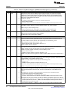
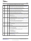
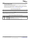
Table 14. I2C Mode Register (ICMDR) Field Descriptions (continued)
Bit Field Value Description
2-0 BC 0-7h Bit count bits. BC defines the number of bits (1 to 8) in the next data word that is to be received or
transmitted by the I2C. The number of bits selected with BC must match the data size of the other
device. Note that when BC = 0, a data word has 8 bits.
If the bit count is less than 8, receive data is right aligned in the D bits of ICDRR and the remaining D
bits are undefined. Also, transmit data written to ICDXR must be right aligned.
0 8 bits per data word
1h 1 bit per data word
2h 2 bits per data word
3h 3 bits per data word
4h 4 bits per data word
5h 5 bits per data word
6h 6 bits per data word
7h 7 bits per data word
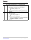
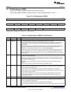
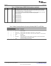
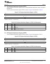
Table 15. Master-Transmitter/Receiver Bus Activity Defined by RM, STT, and STP Bits
ICMDR Bit
RM STT STP Bus Activity
(1)
Description
0 0 0 None No activity
0 0 1 P STOP condition
0 1 0 S-A-D..(n)..D START condition, slave address, n data words (n = value in ICCNT)
0 1 1 S-A-D..(n)..D-P START condition, slave address, n data words, STOP condition (n = value in ICCNT)
1 0 0 None No activity
1 0 1 P STOP condition
1 1 0 S-A-D-D-D.. Repeat mode transfer: START condition, slave address, continuous data transfers
until STOP condition or next START condition
1 1 1 None Reserved bit combination (No activity)
(1)
A = Address; D = Data word; P = STOP condition; S = START condition
34
Inter-Integrated Circuit (I2C) Peripheral SPRUEN0D–March 2011
Submit Documentation Feedback
© 2011, Texas Instruments Incorporated