


Registers
www.ti.com
2.16 Emulation Considerations
The response of the I2C events to emulation suspend events (such as halts and breakpoints) is controlled
by the FREE bit in the I2C mode register (ICMDR). The I2C peripheral either stops exchanging data
(FREE = 0) or continues to run (FREE = 1) when an emulation suspend event occurs. How the I2C
peripheral terminates data transactions is affected by whether the I2C peripheral is acting as a master or a
slave. For more information, see the description of the FREE bit in ICMDR (see Section 3.9).
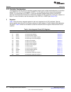
3 Registers
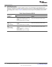
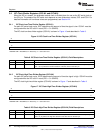
Table 4 lists the memory-mapped registers for the inter-integrated circuit (I2C) peripheral. See the
device-specific data manual for the memory address of these registers. All other register offset addresses
not listed in Table 4 should be considered as reserved locations and the register contents should not be
modified.
Table 4. Inter-Integrated Circuit (I2C) Registers
Offset Acronym Register Description Section
0h ICOAR I2C Own Address Register Section 3.1
4h ICIMR I2C Interrupt Mask Register Section 3.2
8h ICSTR I2C Interrupt Status Register Section 3.3
Ch ICCLKL I2C Clock Low-Time Divider Register Section 3.4
10h ICCLKH I2C Clock High-Time Divider Register Section 3.4
14h ICCNT I2C Data Count Register Section 3.5
18h ICDRR I2C Data Receive Register Section 3.6
1Ch ICSAR I2C Slave Address Register Section 3.7
20h ICDXR I2C Data Transmit Register Section 3.8
24h ICMDR I2C Mode Register Section 3.9
28h ICIVR I2C Interrupt Vector Register Section 3.10
2Ch ICEMDR I2C Extended Mode Register Section 3.11
30h ICPSC I2C Prescaler Register Section 3.12
34h ICPID1 I2C Peripheral Identification Register 1 Section 3.13
38h ICPID2 I2C Peripheral Identification Register 2 Section 3.13
22
Inter-Integrated Circuit (I2C) Peripheral SPRUEN0D–March 2011
Submit Documentation Feedback
© 2011, Texas Instruments Incorporated