


S
1
1 1 1 1 0 A A
7
A A A A A A A AACK0
11
8
ACK
1
Data
n
ACK
1
P
1
A A = 2 MSBs R/W 8 LSBs of slave address
DataDataS
1
DataACK ACK ACK P
1
n n n
111
1
7 n 7 n
1 1 1 1 1 1 1 1
S Slave address
R/W
ACK
Data
ACK
S Slave address
R/W ACK
Data
ACK
P
1 Any
number
1 Any number
Peripheral Architecture
www.ti.com
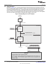
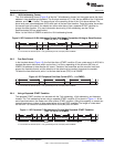
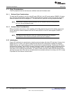
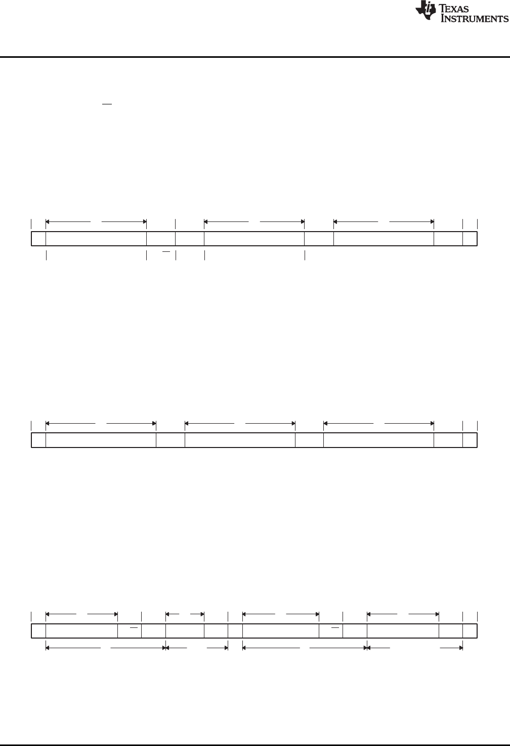
2.6.2 10-Bit Addressing Format
The 10-bit addressing format (Figure 9) is like the 7-bit addressing format, but the master sends the slave
address in two separate byte transfers. The first byte consists of 11110b, the two MSBs of the 10-bit slave
address, and R/W = 0 (write). The second byte is the remaining 8 bits of the 10-bit slave address. The
slave must send acknowledgment (ACK) after each of the two byte transfers. Once the master has written
the second byte to the slave, the master can either write data or use a repeated START condition to
change the data direction. (For more information about using 10-bit addressing, see the Philips
Semiconductors I2C-bus specification.)
Write 1 to the XA bit of ICMDR to select the 10-bit addressing format.
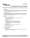
Figure 9. I2C Peripheral 10-Bit Addressing Format With Master-Transmitter Writing to Slave-Receiver
(FDF = 0, XA = 1 in ICMDR)
n = The number of data bits (from 1 to 8) specified by the bit count (BC) field of ICMDR.
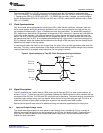
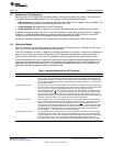
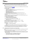
2.6.3 Free Data Format
In the free data format (Figure 10), the first bits after a START condition (S) are a data word. An ACK bit is
inserted after each data word, which can be from 1 to 8 bits, depending on the bit count (BC) bits of
ICMDR. No address or data-direction bit is sent. Therefore, the transmitter and the receiver must both
support the free data format, and the direction of the data must be constant throughout the transfer.
To select the free data format, write 1 to the free data format (FDF) bit of ICMDR.
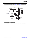
Figure 10. I2C Peripheral Free Data Format (FDF = 1 in ICMDR)
n = The number of data bits (from 1 to 8) specified by the bit count (BC) field of ICMDR.
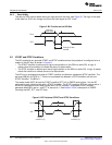
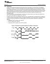
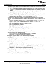
2.6.4 Using a Repeated START Condition
The repeated START condition can be used with the 7-bit addressing, 10-bit addressing, and free data
formats. The 7-bit addressing format using a repeated START condition (S) is shown in Figure 11. At the
end of each data word, the master can drive another START condition. Using this capability, a master can
transmit/receive any number of data words before driving a STOP condition. The length of a data word
can be from 1 to 8 bits and is selected with the bit count (BC) bits of ICMDR.
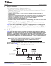
Figure 11. I2C Peripheral 7-Bit Addressing Format With Repeated START Condition
(FDF = 0, XA = 0 in ICMDR)
n = The number of data bits (from 1 to 8) specified by the bit count (BC) field of ICMDR.
14
Inter-Integrated Circuit (I2C) Peripheral SPRUEN0D–March 2011
Submit Documentation Feedback
© 2011, Texas Instruments Incorporated