


www.ti.com
Registers
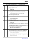
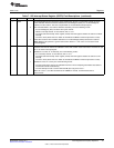
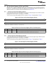
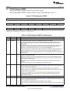
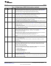
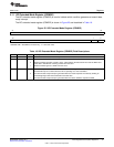
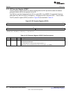
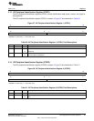
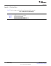
Table 14. I2C Mode Register (ICMDR) Field Descriptions (continued)
Bit Field Value Description
10 MST Master mode bit. MST determines whether the I2C is in the slave mode or the master mode. MST is
automatically changed from 1 to 0 when the I2C master generates a STOP condition. See Table 16.
0 Slave mode. The I2C is a slave and receives the serial clock from the master.
1 Master mode. The I2C is a master and generates the serial clock on the SCL pin.
9 TRX Transmitter mode bit. When relevant, TRX selects whether the I2C is in the transmitter mode or the
receiver mode. Table 16 summarizes when TRX is used and when it is a don't care.
0 Receiver mode. The I2C is a receiver and receives data on the SDA pin.
1 Transmitter mode. The I2C is a transmitter and transmits data on the SDA pin.
8 XA Expanded address enable bit.
0 7-bit addressing mode (normal address mode). The I2C transmits 7-bit slave addresses (from bits 6-0 of
ICSAR), and its own slave address has 7 bits (bits 6-0 of ICOAR).
1 10-bit addressing mode (expanded address mode). The I2C transmits 10-bit slave addresses (from bits
9-0 of ICSAR), and its own slave address has 10 bits (bits 9-0 of ICOAR).
7 RM Repeat mode bit (only applicable when the I2C is a master). The RM, STT, and STP bits determine
when the I2C starts and stops data transmissions (see Table 15). If the I2C is configured in slave mode,
the RM bit is don't care.
0 Nonrepeat mode. The value in the data count register (ICCNT) determines how many data words are
received/transmitted by the I2C.
1 Repeat mode. Data words are continuously received/transmitted by the I2C until the STP bit is manually
set to 1, regardless of the value in ICCNT.
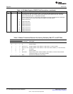
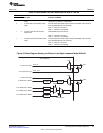
6 DLB Digital loopback mode bit (only applicable when the I2C is a master-transmitter). This bit disables or
enables the digital loopback mode of the I2C. The effects of this bit are shown in Figure 23. Note that
DLB mode in the free data format mode (DLB = 1 and FDF = 1) is not supported.
0 Digital loopback mode is disabled.
1 Digital loopback mode is enabled. In this mode, the MST bit must be set to 1 and data transmitted out
of ICDXR is received in ICDRR after n clock cycles by an internal path, where:
n = ((I2C input clock frequency/prescaled module clock frequency) × 8)
The transmit clock is also the receive clock. The address transmitted on the SDA pin is the address in
ICOAR.
5 IRS I2C reset bit. Note that if IRS is reset during a transfer, it can cause the I2C bus to hang (SDA and SCL
are in a high-impedance state).
0 The I2C is in reset/disabled. When this bit is cleared to 0, all status bits (in ICSTR) are set to their
default values.
1 The I2C is enabled.
4 STB START byte mode bit (only applicable when the I2C is a master). As described in version 2.1 of the
Philips I2C-bus specification, the START byte can be used to help a slave that needs extra time to
detect a START condition. When the I2C is a slave, the I2C ignores a START byte from a master,
regardless of the value of the STB bit.
0 The I2C is not in the START byte mode.
1 The I2C is in the START byte mode. When you set the START condition bit (STT), the I2C begins the
transfer with more than just a START condition. Specifically, it generates:
1. A START condition
2. A START byte (0000 0001b)
3. A dummy acknowledge clock pulse
4. A repeated START condition
The I2C sends the slave address that is in ICSAR.
3 FDF Free data format mode bit. Note that DLB mode in the free data format mode (DLB = 1 and FDF = 1) is
not supported. See Table 16.
0 Free data format mode is disabled. Transfers use the 7-/10-bit addressing format selected by the XA bit.
1 Free data format mode is enabled.
33
SPRUEN0D–March 2011 Inter-Integrated Circuit (I2C) Peripheral
Submit Documentation Feedback
© 2011, Texas Instruments Incorporated