


Registers
www.ti.com
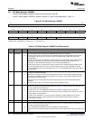
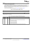
3.9 I2C Mode Register (ICMDR)
The I2C mode register (ICMDR) contains the control bits of the I2C.
The I2C mode register (ICMDR) is shown in shown in Figure 22 and described in Table 14.
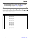
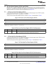
Figure 22. I2C Mode Register (ICMDR)
31 16
Reserved
R-0
15 14 13 12 11 10 9 8
NACKMOD FREE STT Reserved STP MST TRX XA
R/W-0 R/W-0 R/W-0 R-0 R/W-0 R/W-0 R/W-0 R/W-0
7 6 5 4 3 2 0
RM DLB IRS STB FDF BC
R/W-0 R/W-0 R/W-0 R/W-0 R/W-0 R/W-0
LEGEND: R/W = Read/Write; R = Read only; -n = value after reset
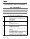
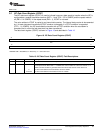
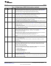
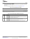
Table 14. I2C Mode Register (ICMDR) Field Descriptions
Bit Field Value Description
31-16 Reserved 0 These reserved bit locations are always read as zeros. A value written to this field has no effect.
15 NACKMOD No-acknowledge (NACK) mode bit (only applicable when the I2C is a receiver).
0 In slave-receiver mode: The I2C sends an acknowledge (ACK) bit to the transmitter during the each
acknowledge cycle on the bus. The I2C only sends a no-acknowledge (NACK) bit if you set the
NACKMOD bit.
In master-receiver mode: The I2C sends an ACK bit during each acknowledge cycle until the internal
data counter counts down to 0. When the counter reaches 0, the I2C sends a NACK bit to the
transmitter. To have a NACK bit sent earlier, you must set the NACKMOD bit.
1 In either slave-receiver or master-receiver mode: The I2C sends a NACK bit to the transmitter during
the next acknowledge cycle on the bus. Once the NACK bit has been sent, NACKMOD is cleared.
To send a NACK bit in the next acknowledge cycle, you must set NACKMOD before the rising edge of
the last data bit.
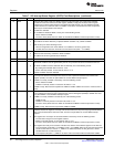
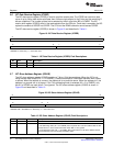
14 FREE This emulation mode bit is used to determine the state of the I2C when a breakpoint is encountered in
the high-level language debugger.
0 When I2C is master: If SCL is low when the breakpoint occurs, the I2C stops immediately and keeps
driving SCL low, whether the I2C is the transmitter or the receiver. If SCL is high, the I2C waits until
SCL becomes low and then stops.
When I2C is slave: A breakpoint forces the I2C to stop when the current transmission/reception is
complete.
1 The I2C runs free; that is, it continues to operate when a breakpoint occurs.
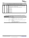
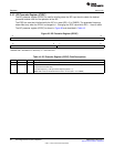
13 STT START condition bit (only applicable when the I2C is a master). The RM, STT, and STP bits determine
when the I2C starts and stops data transmissions (see Table 15). Note that the STT and STP bits can
be used to terminate the repeat mode.
0 In master mode, STT is automatically cleared after the START condition has been generated.
In slave mode, if STT is 0, the I2C does not monitor the bus for commands from a master. As a result,
the I2C performs no data transfers.
1 In master mode, setting STT to 1 causes the I2C to generate a START condition on the I2C-bus.
In slave mode, if STT is 1, the I2C monitors the bus and transmits/receives data in response to
commands from a master.
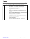
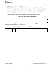
12 Reserved 0 These reserved bit locations are always read as zeros. A value written to this field has no effect.
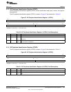
11 STP STOP condition bit (only applicable when the I2C is a master). The RM, STT, and STP bits determine
when the I2C starts and stops data transmissions (see Table 15). Note that the STT and STP bits can
be used to terminate the repeat mode.
0 STP is automatically cleared after the STOP condition has been generated.
1 STP has been set to generate a STOP condition when the internal data counter of the I2C counts down
to 0.
32
Inter-Integrated Circuit (I2C) Peripheral SPRUEN0D–March 2011
Submit Documentation Feedback
© 2011, Texas Instruments Incorporated