


www.ti.com
List of Figures
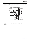
1 I2C Peripheral Block Diagram............................................................................................. 8
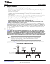
2 Multiple I2C Modules Connected ......................................................................................... 9
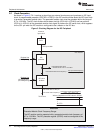
3 Clocking Diagram for the I2C Peripheral ............................................................................... 10
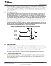
4 Synchronization of Two I2C Clock Generators During Arbitration .................................................. 11
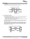
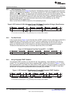
5 Bit Transfer on the I2C-Bus .............................................................................................. 12
6 I2C Peripheral START and STOP Conditions ......................................................................... 12
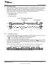
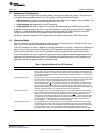
7 I2C Peripheral Data Transfer ............................................................................................ 13
8 I2C Peripheral 7-Bit Addressing Format (FDF = 0, XA = 0 in ICMDR)............................................. 13
9 I2C Peripheral 10-Bit Addressing Format With Master-Transmitter Writing to Slave-Receiver (FDF = 0,
XA = 1 in ICMDR) ......................................................................................................... 14
10 I2C Peripheral Free Data Format (FDF = 1 in ICMDR) .............................................................. 14
11 I2C Peripheral 7-Bit Addressing Format With Repeated START Condition (FDF = 0, XA = 0 in ICMDR) .... 14
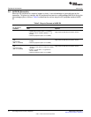
12 Arbitration Procedure Between Two Master-Transmitters ........................................................... 17
13 I2C Own Address Register (ICOAR).................................................................................... 23
14 I2C Interrupt Mask Register (ICIMR).................................................................................... 24
15 I2C Interrupt Status Register (ICSTR) .................................................................................. 25
16 I2C Clock Low-Time Divider Register (ICCLKL) ...................................................................... 28
17 I2C Clock High-Time Divider Register (ICCLKH) ..................................................................... 28
18 I2C Data Count Register (ICCNT)....................................................................................... 29
19 I2C Data Receive Register (ICDRR).................................................................................... 30
20 I2C Slave Address Register (ICSAR)................................................................................... 30
21 I2C Data Transmit Register (ICDXR) ................................................................................... 31
22 I2C Mode Register (ICMDR) ............................................................................................. 32
23 Block Diagram Showing the Effects of the Digital Loopback Mode (DLB) Bit..................................... 35
24 I2C Interrupt Vector Register (ICIVR)................................................................................... 36
25 I2C Extended Mode Register (ICEMDR) ............................................................................... 37
26 I2C Prescaler Register (ICPSC) ......................................................................................... 38
27 I2C Peripheral Identification Register 1 (ICPID1) ..................................................................... 39
28 I2C Peripheral Identification Register 2 (ICPID2) ..................................................................... 39
4
List of Figures SPRUEN0D–March 2011
Submit Documentation Feedback
© 2011, Texas Instruments Incorporated