


Registers
www.ti.com
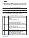
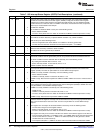
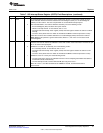
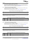
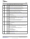
Table 7. I2C Interrupt Status Register (ICSTR) Field Descriptions (continued)
Bit Field Value Description
10 XSMT Transmit shift register empty bit. XSMT indicates that the transmitter has experienced underflow.
Underflow occurs when the transmit shift register (ICXSR) is empty but the data transmit register
(ICDXR) has not been loaded since the last ICDXR-to-ICXSR transfer. The next ICDXR-to-ICXSR
transfer will not occur until new data is in ICDXR. If new data is not transferred in time, the previous
data may be re-transmitted on the SDA pin.
0 Underflow is detected.
1 No underflow is detected. XSMT is set by one of the following events:
• Data is written to ICDXR.
• The I2C is reset (either when 0 is written to the IRS bit of ICMDR or when the processor is reset).
9 AAS Addressed-as-slave bit.
0 The AAS bit has been cleared by a repeated START condition or by a STOP condition.
1 AAS is set by one of the following events:
• I2C has recognized its own slave address or an address of all zeros (general call).
• The first data word has been received in the free data format (FDF = 1 in ICMDR).
8 AD0 Address 0 bit.
0 AD0 has been cleared by a START or STOP condition.
1 An address of all zeros (general call) is detected.
7-6 Reserved 0 These reserved bit locations are always read as zeros. A value written to this field has no effect.
5 SCD Stop condition detected bit. SCD indicates when a STOP condition has been detected on the I2C bus.
The STOP condition could be generated by the I2C or by another I2C device connected to the bus.
0 No STOP condition has been detected. SCD is cleared by one of the following events:
• By reading the INTCODE bits in ICIVR as 110b.
• SCD is manually cleared. To clear this bit, write a 1 to it.
1 A STOP condition has been detected.
4 ICXRDY Transmit-data-ready interrupt flag bit. ICXRDY indicates that the data transmit register (ICDXR) is ready
to accept new data because the previous data has been copied from ICDXR to the transmit shift
register (ICXSR). The CPU can poll ICXRDY or use the XRDY interrupt request.
0 ICDXR is not ready. ICXRDY is cleared by one of the following events:
• Data is written to ICDXR.
• ICXRDY is manually cleared. To clear this bit, write a 1 to it.
1 ICDXR is ready. Data has been copied from ICDXR to ICXSR. ICXRDY is forced to 1 when the I2C is
reset.
3 ICRRDY Receive-data-ready interrupt flag bit. ICRRDY indicates that the data receive register (ICDRR) is ready
to be read because data has been copied from the receive shift register (ICRSR) to ICDRR. The CPU
can poll ICRRDY or use the RRDY interrupt request.
0 ICDRR is not ready. ICRRDY is cleared by one of the following events:
• ICDRR is read.
• ICRRDY is manually cleared. To clear this bit, write a 1 to it.
• The I2C is reset (either when 0 is written to the IRS bit of ICMDR or when the processor is reset).
1 ICDRR is ready. Data has been copied from ICRSR to ICDRR.
2 ARDY Register-access-ready interrupt flag bit (only applicable when the I2C is in the master mode). ARDY
indicates that the I2C registers are ready to be accessed because the previously programmed address,
data, and command values have been used. The CPU can poll ARDY or use the ARDY interrupt
request.
0 The registers are not ready to be accessed. ARDY is cleared by one of the following events:
• The I2C starts using the current register contents.
• ARDY is manually cleared. To clear this bit, write a 1 to it.
• The I2C is reset (either when 0 is written to the IRS bit of ICMDR or when the processor is reset).
1 The registers are ready to be accessed. This bit is set after the slave address appears on the I2C bus.
• In the nonrepeat mode (RM = 0 in ICMDR): If STP = 0 in ICMDR, ARDY is set when the internal data
counter counts down to 0. If STP = 1, ARDY is not affected (instead, the I2C generates a STOP
condition when the counter reaches 0).
• In the repeat mode (RM = 1): ARDY is set at the end of each data word transmitted from ICDXR.
26
Inter-Integrated Circuit (I2C) Peripheral SPRUEN0D–March 2011
Submit Documentation Feedback
© 2011, Texas Instruments Incorporated