


d
7
6
5
PLL1
I2C
prescaler
Prescaled module clock
−−MUST be set to 6.7 to 13.3 MHz
I2C input clock
External
input clock
Register bits
(ICPSC[IPSC])
I2C clock
dividers
Register bits
(ICCLKL[ICCL]),
(ICCLKH[ICCH])
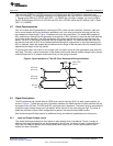
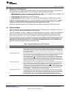
Prescaled module clock frequency =
I2C input clock frequency
(IPSC + 1)
I2C module
I2C serial clock on SCL pin
To I2C bus
I2C serial clock frequency =
prescaled module clock frequency
(ICCL + d) + (ICCH + d)
Where d depends on IPSC value in ICPSC:
IPSC value
0
1
2h−FFh
Peripheral Architecture
www.ti.com
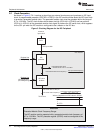
2.2 Clock Generation
As shown in Figure 3, PLL1 receives a signal from an external clock source and produces an I2C input
clock. A programmable prescaler (IPSC bit in ICPSC) in the I2C module divides down the I2C input clock
to produce a prescaled module clock. The prescaled module clock must be operated within the range of
6.7 to 13.3 MHz. The I2C clock dividers divide-down the high (ICCH bit in ICCLKH) and low portions
(ICCL bit in ICCLKL) of the prescaled module clock signal to produce the I2C serial clock, which appears
on the SCL pin when the I2C module is configured to be a master on the I2C bus.
Figure 3. Clocking Diagram for the I2C Peripheral
CAUTION
Prescaled Module Clock Frequency Range:
The I2C module must be operated with a prescaled module clock frequency of
6.7 to 13.3 MHz. The I2C prescaler register (ICPSC) must be configured to this
frequency range.
10
Inter-Integrated Circuit (I2C) Peripheral SPRUEN0D–March 2011
Submit Documentation Feedback
© 2011, Texas Instruments Incorporated