


www.ti.com
Peripheral Architecture
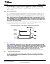
2.7 Endianness Considerations
When the device is configured for big-endian mode, in order for the data to be placed in the right side of
the register being accessed, access to the I2C registers must be performed as follows:
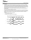
• 8-bit accesses: An offset of 3h must be added to the address of the register being accessed. For
example, the offset address of ICDRR becomes 1Bh (18h + 3h).
• 16-bit accesses: Not supported for the I2C peripheral.
• 32-bit accesses: No offset is needed. For example, the offset address of ICDRR remains as 18h.
In general, software programs the CPU to use 32-bit reads and writes when accessing the I2C registers;
therefore, no offset is needed. However, software usually programs the EDMA to read and write 8-bit
values from the ICDDR and ICDXR registers; hence, the offset must be added.
No offset is needed to access the I2C registers when the device is configured in little-endian mode.
2.8 Operating Modes
The I2C peripheral has four basic operating modes to support data transfers as a master and as a slave.
See Table 1 for the names and descriptions of the modes.
If the I2C peripheral is a master, it begins as a master-transmitter and, typically, transmits an address for a
particular slave. When giving data to the slave, the I2C peripheral must remain a master-transmitter. In
order to receive data from a slave, the I2C peripheral must be changed to the master-receiver mode.
If the I2C peripheral is a slave, it begins as a slave-receiver and, typically, sends acknowledgment when it
recognizes its slave address from a master. If the master will be sending data to the I2C peripheral, the
peripheral must remain a slave-receiver. If the master has requested data from the I2C peripheral, the
peripheral must be changed to the slave-transmitter mode.
Table 1. Operating Modes of the I2C Peripheral
Operating Mode Description
Slave-receiver mode The I2C peripheral is a slave and receives data from a master. All slave modules begin in this
mode. In this mode, serial data bits received on SDA are shifted in with the clock pulses that are
generated by the master. As a slave, the I2C peripheral does not generate the clock signal, but it
can hold SCL low while the intervention of the processor is required (RSFULL = 1 in ICSTR) after
data has been received.
Slave-transmitter mode The I2C peripheral is a slave and transmits data to a master. This mode can only be entered from
the slave-receiver mode; the I2C peripheral must first receive a command from the master. When
you are using any of the 7-bit/10-bit addressing formats, the I2C peripheral enters its
slave-transmitter mode if the slave address is the same as its own address (in ICOAR) and the
master has transmitted R/W = 1. As a slave-transmitter, the I2C peripheral then shifts the serial
data out on SDA with the clock pulses that are generated by the master. While a slave, the I2C
peripheral does not generate the clock signal, but it can hold SCL low while the intervention of the
processor is required (XSMT = 0 in ICSTR) after data has been transmitted.
Master-receiver mode The I2C peripheral is a master and receives data from a slave. This mode can only be entered
from the master-transmitter mode; the I2C peripheral must first transmit a command to the slave.
When you are using any of the 7-bit/10-bit addressing formats, the I2C peripheral enters its
master-receiver mode after transmitting the slave address and R/W = 1. Serial data bits on SDA
are shifted into the I2C peripheral with the clock pulses generated by the I2C peripheral on SCL.
The clock pulses are inhibited and SCL is held low when the intervention of the processor is
required (RSFULL = 1 in ICSTR) after data has been received.
Master-transmitter mode The I2C peripheral is a master and transmits control information and data to a slave. All master
modules begin in this mode. In this mode, data assembled in any of the 7-bit/10-bit addressing
formats is shifted out on SDA. The bit shifting is synchronized with the clock pulses generated by
the I2C peripheral on SCL. The clock pulses are inhibited and SCL is held low when the
intervention of the processor is required (XSMT = 0 in ICSTR) after data has been transmitted.
15
SPRUEN0D–March 2011 Inter-Integrated Circuit (I2C) Peripheral
Submit Documentation Feedback
© 2011, Texas Instruments Incorporated