


www.ti.com
Peripheral Architecture
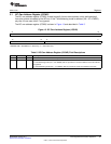
2.13 Interrupt Support
The is capable of interrupting the DSP CPU. The CPU can determine which I2C events caused the
interrupt by reading the I2C interrupt vector register (ICIVR). ICIVR contains a binary-coded interrupt
vector type to indicate which interrupt has occurred. Reading ICIVR clears the interrupt flag; if other
interrupts are pending, a new interrupt is generated. If there is more than one pending interrupt flag,
reading ICIVR clears the highest-priority interrupt flag.
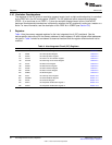
2.13.1 Interrupt Events and Requests
The I2C peripheral can generate the interrupts described in Table 3. Each interrupt has a flag bit in the
I2C interrupt status register (ICSTR) and a mask bit in the interrupt mask register (ICIMR). When one of
the specified events occurs, its flag bit is set. If the corresponding mask bit is 0, the interrupt request is
blocked; if the mask bit is 1, the request is forwarded to the CPU as an I2C interrupt.
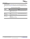
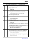
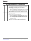
Table 3. Descriptions of the I2C Interrupt Events
I2C Interrupt Initiating Event
Arbitration-lost interrupt (AL) Generated when the I2C arbitration procedure is lost or illegal START/STOP conditions
occur
No-acknowledge interrupt (NACK) Generated when the master I2C does not receive any acknowledge from the receiver
Registers-ready-for-access interrupt Generated by the I2C when the previously programmed address, data and command have
(ARDY) been performed and the status bits have been updated. This interrupt is used to let the
controlling processor know that the I2C registers are ready to be accessed.
Receive interrupt/status (ICRINT Generated when the received data in the receive-shift register (ICRSR) has been copied into
and ICRRDY) the ICDRR. The ICRRDY bit can also be polled by the CPU to read the received data in the
ICDRR.
Transmit interrupt/status (ICXINT Generated when the transmitted data has been copied from ICDXR to the transmit-shift
and ICXRDY) register (ICXSR) and shifted out on the SDA pin. This bit can also polled by the CPU to write
the next transmitted data into the ICDXR.
Stop-Condition-Detection interrupt Generated when a STOP condition has been detected
(SCD)
Address-as-Slave interrupt (AAS) Generated when the I2C has recognized its own slave address or an address of all (8)
zeros.
2.13.2 Interrupt Multiplexing
The I2C interrupt to the DSP CPU are not multiplexed with any other interrupt source.
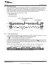
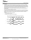
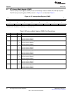
2.14 DMA Events Generated by the I2C Peripheral
For the EDMA controller to handle transmit and receive data, the I2C peripheral generates the following
two EDMA events. Activity in EDMA channels can be synchronized to these events.
• Receive event (ICREVT): When receive data has been copied from the receive shift register (ICRSR)
to the data receive register (ICDRR), the I2C peripheral sends an REVT signal to the EDMA controller.
In response, the EDMA controller can read the data from ICDRR.
• Transmit event (ICXEVT): When transmit data has been copied from the data transmit register
(ICDXR) to the transmit shift register (ICXSR), the I2C peripheral sends an XEVT signal to the EDMA
controller. In response, the EDMA controller can write the next transmit data value to ICDXR.
2.15 Power Management
The I2C peripheral can be placed in reduced-power modes to conserve power during periods of low
activity. The power management of the I2C peripheral is controlled by the processor Power and Sleep
Controller (PSC). The PSC acts as a master controller for power management for all of the peripherals on
the device. For detailed information on power management procedures using the PSC, see the
TMS320C642x DSP Power and Sleep Controller (PSC) User's Guide (SPRUEN8).
21
SPRUEN0D–March 2011 Inter-Integrated Circuit (I2C) Peripheral
Submit Documentation Feedback
© 2011, Texas Instruments Incorporated