


Registers
www.ti.com
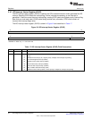
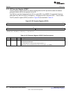
3.10 I2C Interrupt Vector Register (ICIVR)
The I2C interrupt vector register (ICIVR) is used by the CPU to determine which event generated the I2C
interrupt. Reading ICIVR clears the interrupt flag; if other interrupts are pending, a new interrupt is
generated. If there are more than one interrupt flag, reading ICIVR clears the highest priority interrupt flag.
Note that you must read (clear) ICIVR before doing another start; otherwise, ICIVR could contain an
incorrect (old interrupt flags) value.
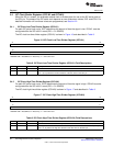
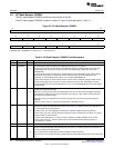
The I2C interrupt vector register (ICIVR) is shown in Figure 24 and described in Table 17.
Figure 24. I2C Interrupt Vector Register (ICIVR)
31 16
Reserved
R-0
15 2 0
Reserved INTCODE
R-0 R-0
LEGEND: R= Read only; -n = value after reset
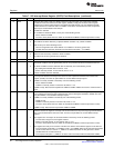
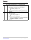
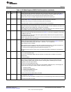
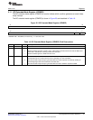
Table 17. I2C Interrupt Vector Register (ICIVR) Field Descriptions
Bit Field Value Description
31-3 Reserved 0 These reserved bit locations are always read as zeros. A value written to this field has no effect.
2-0 INTCODE 0-7h Interrupt code bits. The binary code in INTCODE indicates which event generated an I2C interrupt.
0 None
1h Arbitration-lost interrupt (AL). Highest priority if multiple I2C interrupts are pending.
2h No-acknowledgment interrupt (NACK)
3h Register-access-ready interrupt (ARDY)
4h Receive-data-ready interrupt (ICRRDY)
5h Transmit-data-ready interrupt (ICXRDY)
6h Stop condition detected interrupt (SCD)
7h Address-as-slave interrupt (AAS). Lowest priority if multiple I2C interrupts are pending.
36
Inter-Integrated Circuit (I2C) Peripheral SPRUEN0D–March 2011
Submit Documentation Feedback
© 2011, Texas Instruments Incorporated