Corrective Maintenance
Maintenance
6Ć70
H Place the instrument on its right side (if not already in this position)
to provide access to the boards upgraded in the firmware upgrade
procedure that follows.
ăStep 2:ăAccess boards within the card cage as follows:
H Ensure that the PRINCIPAL POWER SWITCH is set to OFF and the
power cord is disconnected.
H Remove the instrument's top panel cover.
H Remove the two plastic board guides from the top of the card cage
(at the left rear of the instrument).
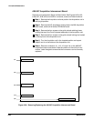
H Remove the three Torx head screws that secure the CRT cover, and
then remove the CRT cover (see Figure 6Ć4).
ăStep 3:ăUpgrade the A15 MMU board firmware as follows:
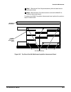
H Remove the A15 MMU board from the card cage. The A15 MMU
board is typically located farthest from the outside (left side) of the
instrument.
H Locate the two firmware ICs, U140 and U150.
CAUTION
To prevent damage to the firmware ICs or the board, ensure pin 1 is
positioned correctly when replacing components.
NOTE
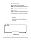
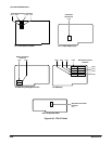
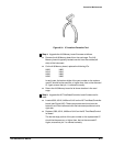
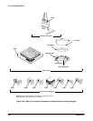
Use the IC InsertionĆExtraction Pliers shown in Figure 6Ć31 for
removing and replacing the ICs. (Refer to Table 4Ć2, Test EquipĆ
ment for the part number of these pliers.)
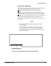
Do not use the label on the IC for an index because it may be
applied incorrectly. (See Figure 6Ć32 for the correct location of the
index on the IC.)
H Remove U140 and replace it with the upgraded IC. The last twoĆdigit
portion of the part number on the replacement IC should be the
same as, or higher than, that on the removed IC. Ensure that pin 1 is
oriented correctly.
H Similarly replace U150 with the upgraded IC.


