Corrective Maintenance
Maintenance
6Ć10
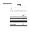
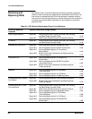
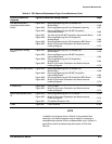
TableĂ6Ć2:ăFRU Removal/Replacement Figure Cross Reference (Cont.)
FRU to be Removed/
Replaced
Figures to Reference During Removal Page
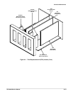
A13 Mother Board Figure 6Ć7 Top View of the Card Cage 6Ć30.............................
Figure 6Ć18 Removing/Replacing the A13 Mother Board 6Ć48..............
Figure 6Ć19 Removing/Replacing the A14 I/O Board 6Ć50..................
Figure 6Ć32 MultiĆPin Connector Orientation and Semiconductor
Indexing Diagram 6Ć74.....................................
A14 Input/Output (I/O)
Board
Figure 6Ć7 Top View of the Card Cage 6Ć30.............................
Figure 6Ć19 Removing/Replacing the A14 I/O Board 6Ć50..................
Figure 6Ć32 MultiĆPin Connector Orientation and Semiconductor
Indexing Diagram 6Ć74.....................................
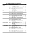
A15 Memory Manager Unit
(MMU) Board
Figure 6Ć7 Top View of the Card Cage 6Ć30.............................
Figure 6Ć19 Removing/Replacing the A14 I/O Board 6Ć50..................
Figure 6Ć20 Removing/Replacing the A15 MMU Board 6Ć52................
Figure 6Ć32 MultiĆPin Connector Orientation and Semiconductor
Indexing Diagram 6Ć74.....................................
A17 Main Processor Board Figure 6Ć7 Top View of the Card Cage 6Ć30.............................
Figure 6Ć21 Removing/Replacing the A17 Main
Processor Board 6Ć54......................................
Figure 6Ć32 MultiĆPin Connector Orientation and Semiconductor
Indexing Diagram 6Ć74.....................................
A18 Memory Board Figure 6Ć7 Top View of the Card Cage 6Ć30.............................
Figure 6Ć22 Removing/Replacing the A18 Memory Board 6Ć56.............
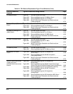
A19 Strobe/TDR Buffer
Board
Figure 6Ć23 Removing/Replacing the A19 Strobe/TDR
Buffer Board 6Ć58..........................................
Figure 6Ć26 Removing/Replacing the A26 M/F Acquisition
Interconnect Board 6Ć62....................................
Figure 6Ć32 MultiĆPin Connector Orientation and Semiconductor
Indexing Diagram 6Ć74.....................................
A20/A21 Head Interconnect
(Power Only) and
A22/A23 Head Interconnect
Boards
Figure 6Ć23 Removing/Replacing the A19 Strobe/TDR
Buffer Board 6Ć58..........................................
Figure 6Ć24 Removing/Replacing the A20/A21 Head Interconnect
(Power Only) and the A22/A23 Head Interconnect Boards 6Ć60..
Figure 6Ć25 Removing/Replacing the Front Subpanel Assembly 6Ć61.......
Figure 6Ć26 Removing/Replacing the A26 M/F Acquisition
Interconnect Board 6Ć62....................................
Figure 6Ć28 Removing/Replacing the A24 Acquisition
Analog Board 6Ć64.........................................
Figure 6Ć29 Removing/Replacing the A28 Acquisition MPU Board 6Ć65......
Figure 6Ć32 MultiĆPin Connector Orientation and Semiconductor
Indexing Diagram 6Ć74.....................................


