Performance Tests
CSA 803A Service Manual
4Ć45
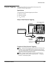
This procedure verifies the correct operation and accuracy of the
CSA 803A's Calibrator.
Measurement Limits
The measurement limits of the calibrator are as follows:
H rise time v250 ps
H 250 mV ±15%
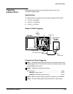
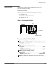
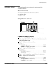
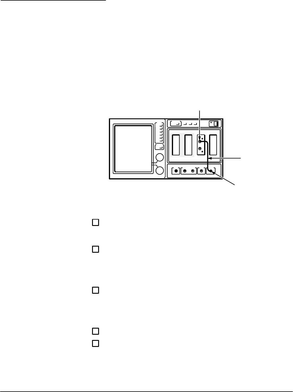
Setup to Examine Calibrator
CSA 803A
Calibrator Output
CH 1
12I RF Cable
Procedure to Examine Calibrator
ăStep 1:ăInstall the SDĆ24 Sampling Head into the position shown in the
setup diagram (CH 1/CH 2 slot). If the unit was in standby mode, set the
ON/STANDBY switch to ON.
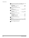
ăStep 2:ăInitialize the mainframe as follows:
UTILITY button press...........................................
Initialize (in major menu) touch..............................
Initialize (in verification popĆup menu) touch..................
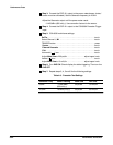
ăStep 3:ăTrigger the CSA 803A as follows:
TRIGGER Button press.........................................
Source (in popĆup menu) Touch..............................
Internal Clock Touch.......................................
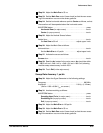
ăStep 4:ăOn the Sampling Head, press the Channel 1 select button.
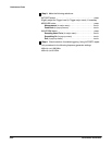
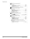
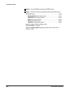
ăStep 5:ăSet up the CSA 803A as follows:
UTILITY Button press...........................................
Instrument Options (in major menu) Touch....................
Edge Mode (in popĆup menu) Touch..........................
Calibrator Output


