Adjustments
CSA 803A Service Manual
5Ć15
ăStep 13:ăTouch Run in the major menu.
ăStep 14:ăExamine that the primary colors (red, green, and blue) are not
separated in the white grid pattern.
WARNING
To prevent electric shock, do not touch the back side of the A7 CRT
Socket board. Use extreme caution when performing the following
adjustment.
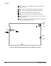
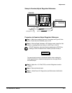
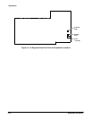
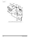
ăStep 15:ăAdjust CONVERGENCE, R210, on the A7 CRT Socket board
for the optimum vertical convergence of the red, green, and blue colors.
ăStep 16:ăExamine that the grid pattern is focused.
ăStep 17:ăAdjust FOCUS, located on the transformer mounted on the A8
CRT Driver board, for the optimum focus of the white grid pattern.
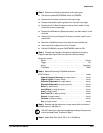
ăStep 18:ăExamine that the grid is aligned with the top and bottom tic
marks along the inside vertical edge of the front panel bezel. To elimiĆ
nate any parallax error, look directly ahead at the CRT, and then align
the top of the grid with the top vertical tic mark and the bottom of the
grid with the bottom tic mark.
ăStep 19:ăAdjust VERT SIZE, L321, and VERT POS, R311, on the A8 CRT
Driver board to align the grid with the tic marks along the inside vertical
edge of the front panel bezel.
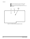
ăStep 20:ăExamine that the grid is aligned with the horizontal tic marks at
the top and bottom of the front panel bezel and that the grid boxes are
of uniform length throughout the grid pattern.
ăStep 21:ăAdjust H SIZE, R501; H LIN, R502; and H POS, R500; on the
A8 CRT Driver board for the best overall linearity and position. Use the
horizontal tic marks at the top and bottom of the front panel bezel to
align the grid.
ăStep 22:ăHĆSIZE, HĆLIN, and HĆPOS potentiometers interact, so you
may need to repeat Steps 20 and 21 until they are all correctly adjusted.
ăStep 23:ăTouch Exit to return to the Routine menu of the Extended
Diagnostic menu structure.
ăStep 24:ăTouch Gray Scale in the Routine menu.
ăStep 25:ăTouch Run in the major menu.


