


36 Chapter 2 Setting/Displaying Time Data and Text Information
Chapter 2 Setting/Displaying Time Data and Text Information
Information displayed
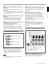
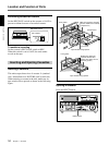
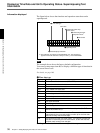
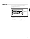
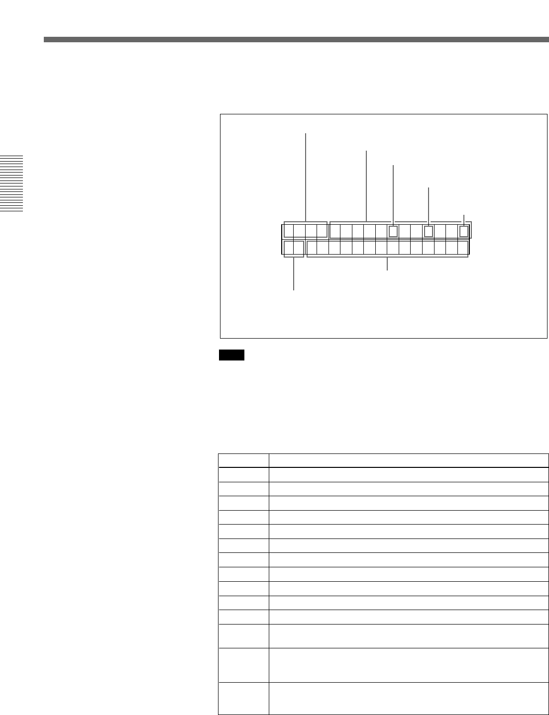
The figure below shows the time data and operation status that can be
superimposed.
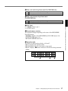
Note
The example above shows the factory default configuration.
You can use setup menu item 005 to display a different type of time data in
the second line as well.
For details, see page 108.
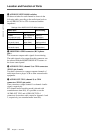
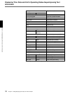
1 Time data type
Display Meaning
CNT Count value of the time counter (COUNTER)
TCR Timecode reader timecode data
UBR Timecode reader user bits data
TCR. VITC reader time code data
UBR. VITC reader user bits data
TCG Timecode generator timecode data
UBG Timecode generator user bits data
IN IN point time data
OUT OUT point time data
AI Audio IN point time data
AO Audio OUT point time data
DUR The duration between any two of the four edit points (IN, OUT,
AUDIO IN, AUDIO OUT)
T*R
a)
Time code data from time code reader. The asterisk indicates an
interpolation by the time code reader to make up for the time code
data not correctly read from the tape.
U*R
a)
User bit data from the time code reader. The asterisk indicates that
last data is retained by the time code reader, as the new data has
not been read correctly from the tape.
a) “*” appears when data has not been correctly read from tape.
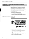
Displaying Time Data and Unit's Operating Status−Superimposing Text
Information
TCR 23 : 59 . 40 . 18 *
PSHUTTLESTILL
a) This character can appear on the DSR-2000 only. The character to
appear in these two columns is always a colon (:) on the DSR-2000P.
4 VITC field
6 Operating mode
5 Recorder/player selection
3 Timecode generator
drop-frame mark
a)
Time data
2 Timecode reader drop-
frame mark
a)
1 Time data type