


Chapter 7 Connections and
Settings
Chapter 7 Connections and Settings 131
2
1
1
2
COMPONENT VIDEO IN
(Y,R−Y,B−Y)
AUDIO
OUT
TIME CODE IN
AUDIO IN
CH-1
AUDIO IN
CH-2
COMPONENT
OUTPUT
CH-1
CH-2
TC OUT
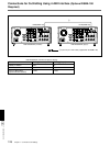
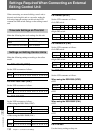
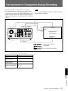
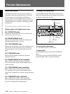
Connections for Component Analog Recording
The following shows connections for a system in
which analog playback signals from another recorder
or player are recorded on the DSR-2000/2000P. In this
system, the video signals are analog component signals
and the audio signals are recorded from audio channels
1 and 2.
Note
In this case, the DSBK-170 Analog Component Iuput/
Output Board is required.
DSR-2000/2000P (recorder) settings
Control Setting
Videocassette recorder/
player such as
UVW-1600/1600P
DSR-2000/2000P
(recorder)
1 Cable with XLR connectors
(not supplied)
2 75 Ω coaxial cable (not supplied)
REMOTE button Unlit
VIDEO IN button (input
selection section)
Y–R, B
CH1,1/2 button and
CH2,3/4 button
ANALOG
AUDIO IN LEVEL/600Ω
switch (connector panel)
Normally, 4 dBm, 600Ω (HIGH-
ON)