


Chapter 1 Overview
Chapter 1 Overview 29
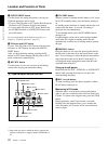
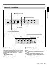
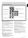
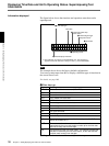
1 Analog video input/output section
REF.VIDEO
ANALOG VIDEO I/O
S VIDEO
TIME CODE
OUT
OUT
OUT
OUT
(SUPER)
IN
IN
IN
1
2
3
IN
OFF
ON
75Ω
VIDEO IN
VIDEO OUT
COMPONENT VIDEO
OFF
ON
75Ω
Y
R-Y
B-Y
5 S VIDEO IN connector
1 REF. VIDEO IN connectors
and 75Ω termination switch
2 REF. VIDEO OUT connector
3 TIME CODE IN connector
4 TIME CODE OUT connector
6 S VIDEO OUT connector
7 VIDEO IN connectors and 75Ω termination
switch
8 COMPONENT VIDEO Y/R−Y/B−Y IN
connectors
9 COMPONENT VIDEO Y/R−Y/
B−Y OUT connectors
!º VIDEO OUT 1, 2, and 3 (SUPER) connectors
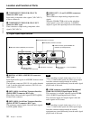
1 REF. (reference) VIDEO IN connectors (BNC
type) and 75Ω termination switch
Input a reference video signal to one of these
connectors. The two connectors can be used for a loop-
through connection. When making a loop-through
connection, set the termination switch to OFF, and
when not, set the switch to ON.
2 REF. (reference) VIDEO OUT connector (BNC
type)
This connector outputs a reference video signal, except
when i.LINK is selected in the input selection section
(see page 14).
3 TIME CODE IN connector (BNC type)
Input SMPTE time code (DSR-2000) or EBU time
code (DSR-2000P) externally generated to this
connector.
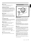
4 TIME CODE OUT connector (BNC type)
This connector outputs a time code according to the
operating state of the unit, as follows:
During playback: the playback time code
During recording: the time code generated by the
internal time code generator or the time code input
to the TIME CODE IN connector.
For more information about the time code output during
recording, see extended setup menu item 611.
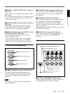
5 S VIDEO IN connector (4-pin)
Input an S-video signal with separated Y (luminance)
and C (chroma: 3.58 MHz for DSR-2000 or 4.43 MHz
for DSR-2000P) components to this connector.
6 S VIDEO OUT connector (4-pin)
This connector outputs an S-video signal with
separated Y (luminance) and C (chroma: 3.58 MHz for
DSR-2000 or 4.43 MHz for DSR-2000P) components.
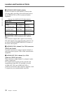
7 VIDEO IN connectors (BNC type) and 75W
termination switch
Input an analog composite video signal to one of these
connectors. The two connectors can be used for a loop-
through connection. When making a loop-through
connection, set the 75Ω termination switch to OFF and
when not, set the switch to ON.