


Appendixes
148 Appendixes
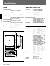
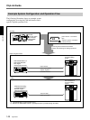
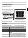
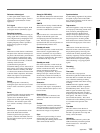
Example System Configuration and Operation Flow
The following illustration shows an example system
configuration for using the ClipLink function and a
typical ClipLink operation flow.
Shooting
DVCAM
camcorder (DSR-
130/130P/300/
300P/500WS/
500WSP)
DVCAM standard cassette or DVCAM mini cassette
Index Pictures: recorded on
tape
ClipLink log data: recorded in
cassette memory
ClipLink log data tranfer
ES-7 EditStation™
non-linear editing
system
DSR-2000/85/80/60
a)
(or
DSR-2000P/85P/80P/
60P
a)
Digital
Videocassette Recorder
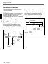
Video output (QSDI)
Index Pictures
ClipLink log data
RS-422A interface
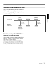
Editing
Actual AV data
QSDI input/output
ES-7 EditStation™
non-linear editing
system
DSR-2000/85
b)
/80/60
a)
(or DSR-2000P/85P
b)
/
80P/60P
a)
Digital
Videocassette Recorder
a) The DSR-60/60P is a videocassette player.
b) Between the DSR-85/85P and ES-7, quadruple transfer is possible through the QSDI.
ClipLink log data recorded onto DVCAM
cassettes links shooting and editing operations.
ClipLink
Guide