


Chapter 1 Overview
Chapter 1 Overview 13
POWER
INPUT SELECT
SDTI/i.LINK
VIDEO IN
REMOTE
9PIN
i.LINK
CH-1,1/2
CH-2,3/4
MIXING
0
2
1
0
-1
-2
-12
dB
OVER
dB
-20
-30
-40
-60
1
0
2
1
0
-1
-2
-12
dB
OVER
dB
-20
-30
-40
-60
2
0
2
1
0
-1
-2
-12
dB
OVER
dB
-20
-30
-40
-60
3
0
2
1
0
-1
-2
-12
dB
OVER
dB
-20
-30
-40
-60
4
INPUT
V:SDTI
COMPOSITE
ANALOG
AES/EBU
ANALOG
SDTI
SDI SG
SDI SG
AES/EBU
SDI SG
Y-R,B
S VIDEO
i.LINK
PB FS
48k44.1k32k
REC MODE
2CH4CH
VIDEO
AUDIO
CH11/2
CH23/4
INPUT
V:SDTI
COMPOSITE
ANALOG
AES/EBU
ANALOG
SDTI
SDI SG
SDI SG
AES/EBU
SDI SG
Y-R,B
S VIDEO
i.LINK
PB FS
48k44.1k32k
REC MODE
2CH4CH
VIDEO
AUDIO
CH11/2
CH23/4
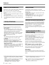
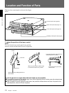
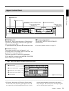
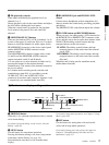
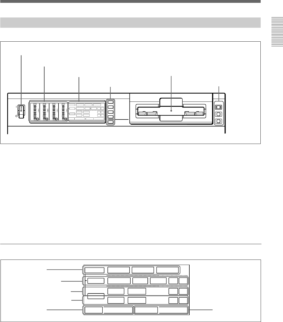
Upper Control Panel
1 POWER switch
2 Audio level meters
3 Cassette compartment
1 Input selection/audio mode display section
(see below)
1 POWER switch
Press the “1” side to power the unit on. When the unit
is powered on, the display windows in the upper and
lower control panels light.
To power the unit off, press the “¬”side of the switch.
2 Audio level meters
These show the audio levels of channels 1 to 4
(recording levels in recording mode or E-E mode
1)
and
playback level in playback mode).
There are two modes for audio level indications:
FULL and FINE, selected by the METER FULL/FINE
button on the lower control panel.
1) E-E mode: Abbreviation of “Electric-to-Electric mode”.
In this mode, video and audio signals input to the VCR
are output after passing through internal electric circuits,
.........................................................................................................................................................................................
3 Cassette compartment
Accepts DVCAM, DV and DVCPRO(25)
videocassettes.
For details of usable cassettes, see page 33.
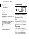
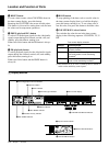
1 Input selection/audio mode display section
1 INPUT display
5 PB FS display
6 REC MODE display
2 INPUT VIDEO display
3 AUDIO CH1, CH1/2 display
4 AUDIO CH2, CH3/4 display
but not through magnetic conversion circuits such as
heads and tapes. This can be used to check input signals
and for adjusting input signal levels.
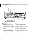
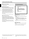
2 Input selection section
(see page 14)
3 Remote control
setting section
(see page 15)