


Chapter 6 Setup Menu
108 Chapter 6 Setup Menu
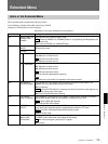
Basic Menu
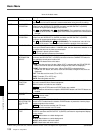
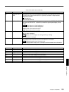
Item number Item name Settings
001 PREROLL TIME 0S... 5S ...30S: Set the preroll time to between 0 and 30 seconds in steps of 1 second.
A preroll time of at least 5 seconds is recommended when using this unit for editing.
002
a)
CHARACTER
H-POSITION
Adjust the horizontal screen position (as a hexadecimal value) of the text information
output from the VIDEO OUT 3 (SUPER) connector and SDI OUTPUT 3 (SUPER)
connector for superimposed display on the monitor.
00... 0A ...2A (DSR-2000) /00... 09 ...29 (DSR-2000P): The hexadecimal value 00 is for
the far left of the screen. Increasing the value moves the position of the characters to
the right.
003
a)
CHARACTER
V-POSITION
Adjust the vertical screen position (as a hexadecimal value) of the text information
output from the VIDEO OUT 3 (SUPER) connector and SDI OUTPUT 3 (SUPER)
connector for superimposed display on the monitor.
00... 2E ...38 (DSR-2000)/00... 37 ...43 (DSR-2000P): The hexadecimal value 00 is for
the top of the screen. Increasing the value lowers the position of the characters.
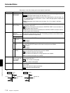
004 SYNCHRONIZE When editing using this unit as a controller and an external VCR connected to this unit
via a 9-pin remote control cable or i. LINK/DV cable, this item determines whether or not
to operate the two units in phase synchronization.
ON : Operate in phase synchronization.
OFF: Do not operate in phase synchronization.
005 DISPLAY
INFORMATION
SELECT
Determine the kind of text information to be output from the VIDEO OUT 3 (SUPER)
connector and SDI OUTPUT 3 (SUPER) connector when the CHARACTER switch on
the subsidiary control panel is set to ON.
T&STA : Time data and the units status.
T&UB: Time data and user bit data. (When U-BIT is selected with the COUNTER SEL
button, the user bit data and time data arranged in that order are displayed.)
T&CNT: Time data and counter count. (When COUNTER is selected with the
COUNTER SEL button, the counter count and time data arranged in that order are
displayed.)
T&T: Time data and time code (TC or VITC).
TIME: Timecode (TC or VITC) only.
DATE: Recording date and time.
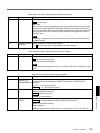
006 LOCAL
FUNCTION
ENABLE
Determine which tape transport control buttons on the control panel are enabled when
this unit is controlled from external equipment.
DIS: All buttons and switches are disabled.
ST&EJ : Only the STOP button and EJECT button are enabled.
ENA: All buttons and switches except the RECORDER button and PLAYER button are
enabled.
007 TAPE TIMER
DISPLAY
Determine whether to display the counter in 12-hour mode or 24-hour mode.
+ –12H : 12-hour mode
24H: 24-hour mode
008 MONITORING
SELECTION FOR
VTR-TO-VTR
EDIT
For editing with two DSR-2000/2000P units, determine whether the recorder unit is
forced into E-E mode when the recorder PLAYER button is pressed to view the player
playback signals on the monitor.
MANU : Do not force the recorder into E-E mode.
AUTO: Force the recorder into E-E mode.
009
a)
CHARACTER
TYPE
Determine the type of characters such as time code output from the VIDEO OUT 3
(SUPER) connector and SDI OUTPUT 3 (SUPER) connector for superimposed display
on the monitor.
WHITE : White letters on a black background.
BLACK: Black letters on a white background.
W/OUT: White letters with black outline.
B/OUT: Black letters with white outline.
Items in the basic menu
(Continued)
a) When setting items 002, 003, and 009, watch the monitor screen, and adjust to the required state.