


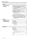
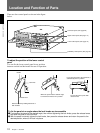
Location and Function of Parts
Chapter 1 Overview
14 Chapter 1 Overview
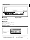
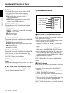
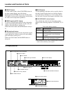
1 INPUT display
Indicates the input signal selected with the SDTI/
i.LINK button in the input selection section.
V:SDTI: Digital video signal in SDTI(QSDI) format
SDTI: Digital video and audio signals in
SDTI(QSDI) format
i.LINK: Digital video and audio signals in DV
format, using i.LINK technology
2 INPUT VIDEO display
Indicates the input video signal selected with the
VIDEO IN button in the input selection section.
COMPOSITE: Composite video signal
Y-R, B: Y, R−Y and B−Y component video signals
S VIDEO: S-video signal
SDI: SDI video signal
SG: Video test signal
3 AUDIO CH1, CH1/2 display
Indicates the input audio signal selected with the CH1,
CH1/2 button in the input selection section.
ANALOG: Analog audio signal
AES/EBU: Digital audio signal in AES/EBU format
SDI: SDI audio signal
SG: Audio test signal
4 AUDIO CH2, CH3/4 display
Indicates the input audio signal selected with the CH2,
CH3/4 button in the input selection section. The
indications available are the same as for the AUDIO
CH1, CH1/2 display described above.
5 PB FS (playback audio sampling frequency)
display
Indicates the sampling frequency (48 kHz, 44.1 kHz or
32 kHz) at which audio is recorded on tape.
6 REC MODE (audio recording mode) display
Indicates the audio recording mode (2CH or 4CH)
selected with extended menu item 817.
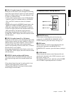
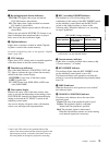
2 Input selection section
1 SDTI/i.LINK (SDTI(QSDI) interface/i.LINK
selection) button
Each press of this button cycles through the following
input signal selection options.
• Digital video signal in SDTI(QSDI) format input to
the SDTI(QSDI) INPUT connector
When this is selected, use the CH1, 1/2 button and
CH2, 3/4 button to select the required input audio
signals.
• Digital video and audio signals in SDTI(QSDI)
format input to the SDTI(QSDI) INPUT connector
• Digital video and audio signals in DV format, using
i.LINK technology, input to the i.LINK connector
(available when the optional DSBK-190 i.LINK/DV
Input/Output Board is installed)
In the input selection/audio mode display section, the
INPUT display shows the selection made with this
button.
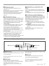
2 VIDEO IN button
Each press of this button cycles through the following
input video signal selection options.
• Composite video signal input to the VIDEO IN
connectors.
• Component video signals input to the COMPONENT
VIDEO Y/R−Y/B−Y IN connectors
• S-video signal input to the S VIDEO IN connector
• SDI video signal input to the SDI INPUT connector
• Video test signal (selected with extended menu item
710) generated by the internal signal generator
In the input selection/audio mode display section, the
INPUT VIDEO display shows the selection made with
this button.
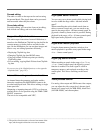
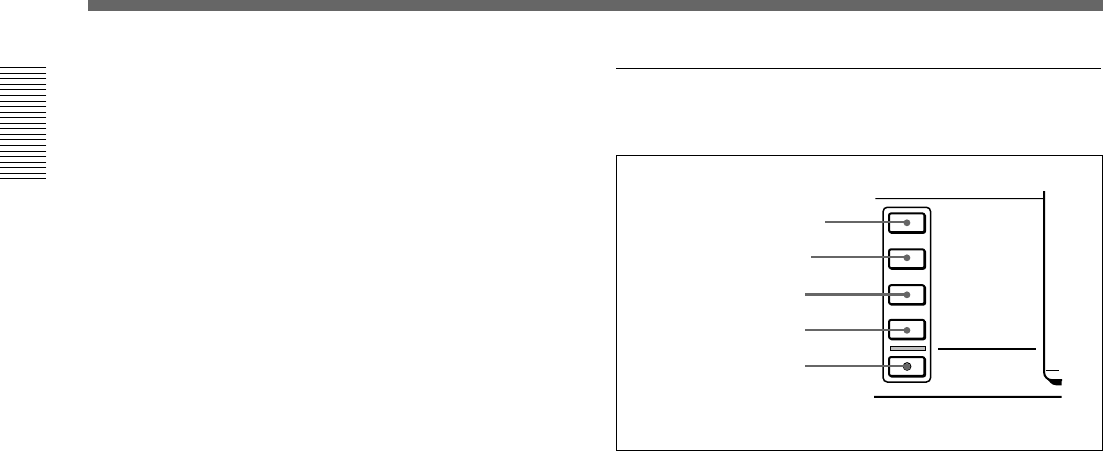
INPUT SELECT
SDTI/i.LINK
VIDEO IN
CH-1,1/2
CH-2,3/4
MIXING
3 CH1, 1/2 button
4 CH2, 3/4 button
5 MIXING button
1 SDTI/i.LINK button
2 VIDEO IN button