


Chapter 1 Overview
Chapter 1 Overview 31
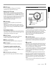
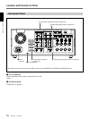
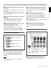
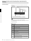
5 DIGITAL AUDIO (AES/EBU) OUT connectors
(BNC type)
These connectors onput digital audio signals in AES/
EBU format.
The left-hand connector (CH-1/2) is for audio channels
1 and 2, and the right-hand connector (CH-3/4) is for
audio channels 3 and 4.
6 SDI (Serial Digital Interface) INPUT connectors
(BNC type)
Input digital video and audio signals in SDI (D1)
format to the left-hand connector. The right-hand
connector is for an active-through connection.
7 SDI (Serial Digital Interface) OUTPUT 1, 2 and
3 (SUPER) connectors (BNC type)
These connectors output digital video and audio
signals in SDI (D1) format.
When the CHARACTER switch on the subsidiary
control panel is set to ON, connector 3 (SUPER)
outputs a signal with superimposed text information.
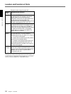
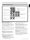
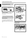
3 External device connectors
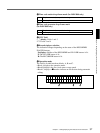
1 VIDEO CONTROL connector (D-sub 15-pin)
For remote control of the internal digital video
processor, connect an optional remote control unit
such as the UVR-60/60P or BVR-50/50P to this
connector.
Note
Always power off this unit before connecting the
remote control unit.
1 VIDEO CONTROL connector
REMOTE-OUT
REMOTE-IN
VIDEO CONTROL
CONTROL PANEL
2 CONTROL PANEL connector
3 REMOTE-IN connector
4 REMOTE-OUT connector
2 CONTROL PANEL connector (D-sub 15-pin)
When using the optional DSBK-200 Control Panel to
remotely control this unit, connect the DSBK-200 to
this connector.
3 REMOTE-IN connector (D-sub 9-pin)
When controlling this unit from an editing controller
such as the ES-7, PVE-500, BVE-600/800/910, or
RM-450/450CE, connect the unit to the editing
controller via this connector using the supplied 9-pin
remote control cable.
When controlling another VCR from this unit, connect
the VCR to this connector.
4 REMOTE-OUT connector (D-sub 9-pin)
This connector provides the loop-through output for
remote control signals from the REMOTE-IN
connector.
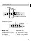
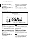
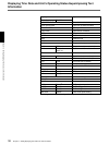
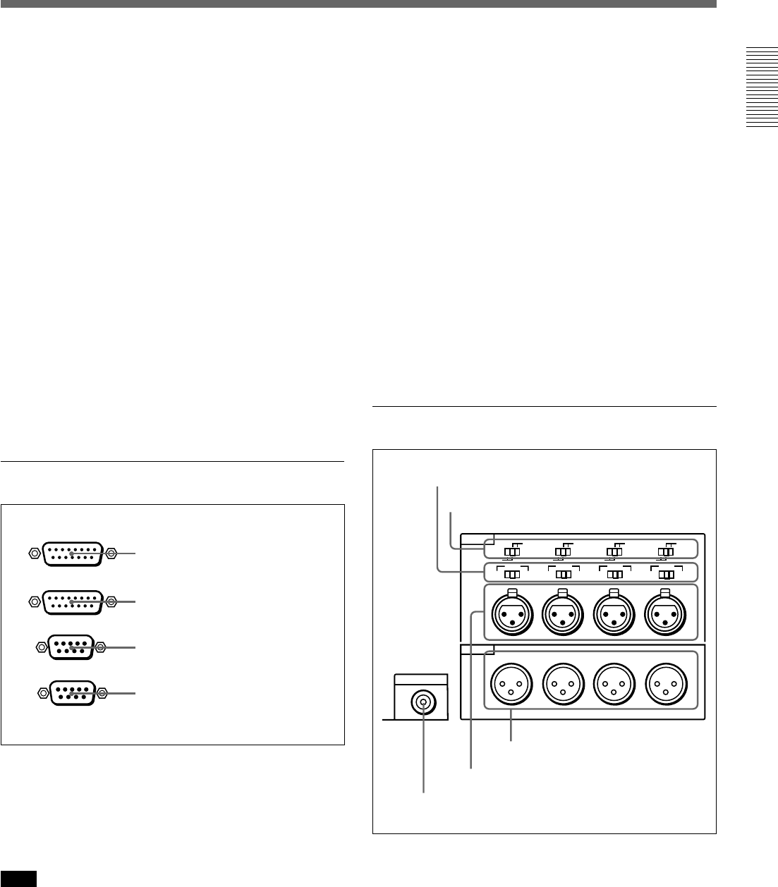
4 Analog audio input/output section
1 AUDIO IN −6dBm/0dBm/+4dBm switches
Set these switches according to the audio input levels
to the AUDIO IN CH-1 to CH-4 connectors.
MONITOR AUDIO
AUDIO IN
LEVEL
AUDIO OUT
CH-1
CH-2 CH-3
CH-4
CH-1
0dBm
HIGHLOW
OFF
-6dBm +4dBm
CH-2 CH-3
CH-4
0dBm
-6dBm +4dBm
0dBm
-6dBm +4dBm
0dBm
-6dBm +4dBm
ON
-600
Ω
LEVEL
HIGHLOW
OFF
ON
-600
Ω
LEVEL
HIGHLOW
OFF
ON
-600
Ω
LEVEL
HIGHLOW
OFF
ON
-600
Ω
1 AUDIO IN −6dBm/0dBm/+4dBm switches
2 AUDIO IN LEVEL/600Ω switches
3 MONITOR AUDIO connector
4 AUDIO IN CH-1 to CH-4 connectors
5AUDIO OUT CH-1 to CH-4
connectors