


Chapter 1 Overview
Chapter 1 Overview 15
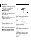
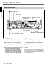
3 CH1, 1/2 (audio channel 1 or 1/2) button
Each press of this button cycles through the following
input audio signal selection options for audio channel 1
(when in 2-channel mode) or for audio channels 1 and
2 (when in 4-channel mode).
• Analog audio signal(s) input to the AUDIO IN CH-1
connector (when in 2-channel mode) or AUDIO IN
CH-1 and CH-2 connectors (when in 4-channel
mode).
• Digital audio signal in AES/EBU format input to the
DIGITAL AUDIO (AES/EBU) CH-1/2 connector
• SDI audio signal input to the SDI INPUT connector
• Audio test signal (selected with extended menu item
808) generated by the internal signal generator
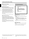
In the input selection/audio mode display section, the
AUDIO CH1, CH1/2 display shows the selection made
with this button.
4 CH2, 3/4 (audio channel 2 or 3/4) button
Each press of this button cycles through the input audio
signal selection options for audio channel 2 (when in 2-
channel mode) or for audio channels 3 and 4 (when in
4-channel mode) The input audio signal selection
options corresponding to those for the CH1, 1/2 button
described above are available.
In the input selection/audio mode display section, the
AUDIO CH2, CH3/4 display shows the selection made
with this button.
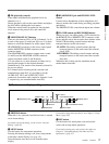
5 MIXING (mixing setting on/off) button
This enables (ON) or disables (OFF) the setting for
audio input mixing made with extended menu item
819.
If the selected signal (except for analog audio) is not
supplied to the appropriate connector, the
corresponding indicator in the input selection/audio
mode display section flashes.
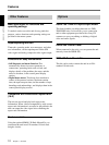
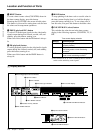
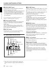
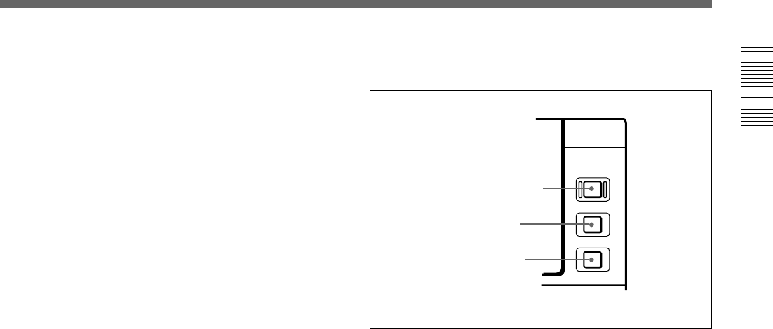
3 Remote control setting section
1 REMOTE button
When remote-controlling this unit from the unit
connected to the REMOTE-IN, REMOTE-OUT or
i.LINK connector, press this button, turning it on.
2 9PIN button
When carrying out remote control between this unit
and the unit connected to the REMOTE-IN or
REMOTE-OUT connector, press this button, turning it
on.
3 i.LINK button
When carrying out remote control between this unit
and the unit connected to the i.LINK connector, press
this button, turning it on.
This button is effective only when the optional DSBK-
190 i.LINK/DV Input/Output Board is installed.
REMOTE
9PIN
i.LINK
2 9PIN button
1 REMOTE button
3 i.LINK button