Advanced Applications
9 - 29
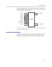
The block diagram of this system is shown in the next figure. The channel
names are labeled with the virtual channel names that are created by default
by the SoundStructure Studio software.
To create this design, start the SoundStructure Studio software and follow the
steps shown in the next section.
SoundStructure Studio Steps
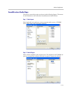
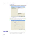
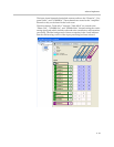
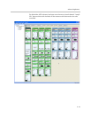
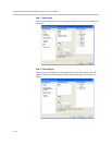
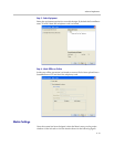
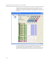
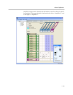
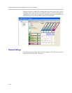
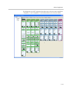
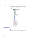
The steps to create this project are shown in the following figures. The names
for the channels are the default names created by SoundStructure Studio,
although the virtual channel names could be set to any valid text string.
SoundStructure
C12 and TEL2
Table Mic 1
Table Mic 2
Table Mic 3
Table Mic 4
Table Mic 5
Table Mic 6
Table Mic 7
Table Mic 8
Program Audio (L)
Program Audio (R)
Phone 1 In
Phone 2 In
Phone 1 Out
Phone 2 Out
Amplifier 1
Amplifier 2


