Customizing SoundStructure Designs
5 - 37
Compressors And Limiters
The peak limiter monitors the peak signal magnitude and compares it to a
threshold. If the peak surpasses the threshold, the peak limiter immediately
attenuates the signal with a very fast attack to bring the peak level below the
threshold.
Limiters and compressors attenuate high-level signals without changing low
level signals and are typically used to prevent loud signals from clipping, or to
reduce the dynamic range of a signal to make the output level more consistent
even if the input level is not consistent. When the input signal level rises above
the compressor’s threshold, the compressor applies attenuation so that the
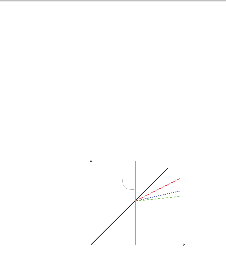
output signal increases at a rate of one over the compression ratio past the
threshold. Signals below the threshold are not modified, signals above the
threshold are “compressed” or scaled by the compression ratio.
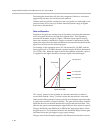
For example, if the compression ratio is set to 4:1, the threshold is set to -10
dBFS
1
, and the input signal level is -2 dBFS (8 dB above the threshold) the com-
pressor applies the compression ratio (in this case 4:1) and divides the 8 dB by
4 to arrive at 2 dB. The output signal is then -8 dBFS (2 dB above the threshold)
even though the input signal was 8 dB above the threshold.
From this example, it is clear that the threshold is not a hard limit, but rather
the onset of when the “compression” or division by the compression ratio is
engaged. This is shown in the following figure.
The “attack” portion of the compressor is when attenuation is increased as the
signal level crosses the threshold, and the “decay” portion is when the attenu-
ation is reduced toward 0 dB as the signal level falls below the threshold.
1
dBFS means dB full scale where 0 dBFS is the maximum input signal allowed.
Due to the SoundStructure design of a nominal signal level of 0 dBu with 20
dB headroom, -20 dBFS equals 0 dBu.
Input Level (dB)
Output Level (dB)
No Compression
2:1 Compression
4:1 Compression
10:1 Compression
Threshold


