Customizing SoundStructure Designs
5 - 49
following table.
These band edges are exactly between the center frequencies. At the band
edges, the gain of the equalizer band is half the gain (in dB) at the center fre-
quency. Adjacent bands in the graphic equalizer bleed over into each other
and affect each others' total gain which can increase the amount of time a user
must spend adjusting the equalizer to arrive at a desired frequency response.
The graphic equalizer provides a gain compensation control that corrects the
gain settings of each band to provide the desired gain specified by the user at
each center frequency.
Delay
The delay processing allows the designer to add from 0 to 1000 milliseconds of
delay on the output channels. While the delay is set in milliseconds in the user
interface, it can be manually set through the command API in samples where
each sample represents 1/48 of a millisecond.
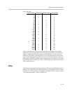
Center Freq (Hz) 1 octave band 2/3 octave band 1/3 octave band
20 — — 0
25 — 0 1
32 0 — 2
40 — 1 3
50 — — 4
63 1 2 5
80 — — 6
100 — 3 7
125 2 — 8
160 — 4 9
200 — — 10
250 3 5 11
315 — — 12
400 — 6 13
500 4 — 14
630 — 7 15
800 — — 16
1,000 5 8 17
1,250 — — 18
1,600 — 9 19
2,000 6 — 20
2,500 — 10 21
3,150 — — 22
4,000 7 11 23
5,000 — — 24
6,300 — 12 25
8,000 8 — 26
10,000 — 13 27
12,500 — — 28
16,000 9 14 29
20,000 — — 30


