Design Guide for the Polycom SoundStructure C16, C12, C8, and SR12
5 - 44
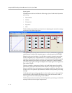
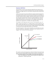
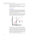
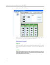
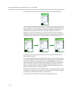
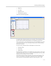
in the digital domain. The fader control is shown in the following figure.
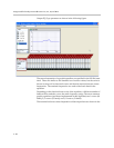
A maximum and minimum gain range can be specified for the input faders to
make it possible to limit user gain control by moving the triangles associated
the gain slider. To set the maximum fader gain, adjust the main slider to the
desired maximum gain and then move the upper triangle to that level.
Similarly to adjust the minimum gain, adjust the main slider to the desired
minimum level and them move the lower triangle to that location. The steps to
set the maximum fader gain to +10 dB are shown in the following figure.
See Chapter 9 for an application where the user minimum and maximum
faders have been used.
It is recommended that any user adjustment of gain control for input signals
control the input fader. This will allow the analog input gain (not the fader) to
be used for calibration of the input device to the SoundStructure device to
ensure the input reaches the 0 dBu nominal signal level of the SoundStructure
device. The fader can then be used to make additional adjustments. This
ensures when the fader is set back to 0 dB that the analog input gain is still
properly calibrated for the connected device.
The signal level meter next to the gain fader shows the signal activity after all
the input processing has been applied. If an input has been muted, the signal
level meter for the fader will show no signal activity.
See Chapter 7 for additional information on setting signal levels.


