


38
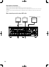
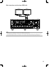
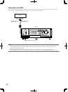
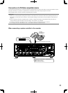
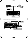
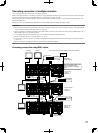
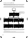
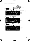
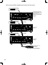
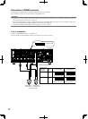
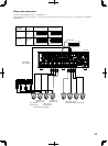
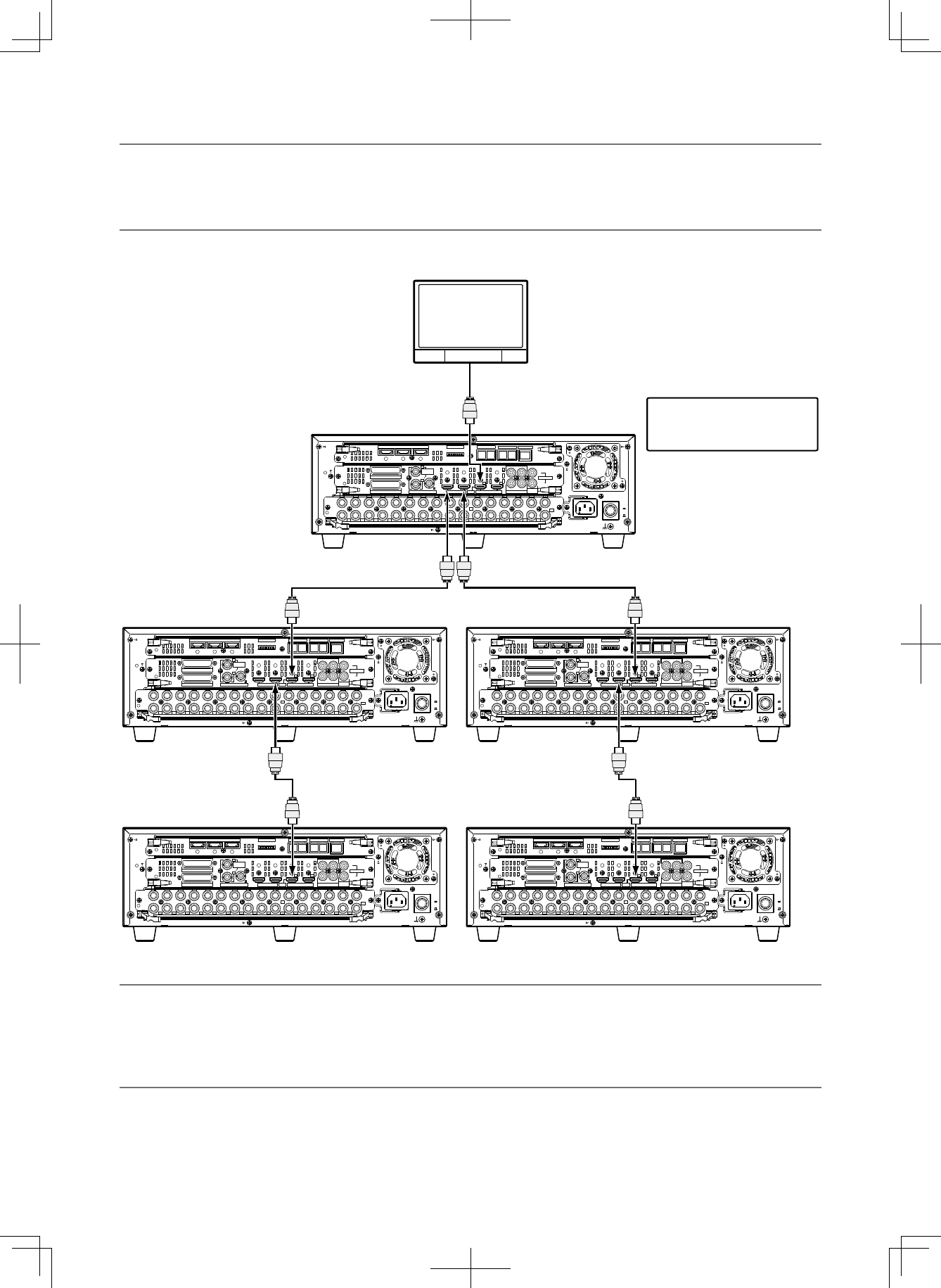
CascadingconnectionusingHDMIcables
Important:
• Upto5recordersandasinglesystemcontrollercanbeconnected.
• Connecttherecorderwhoseunitaddress(system)isevennumbertothecascadeinput1connectorofthefirstrecorder.
Connect the recorder whose unit address (system) is odd number to the cascade input 2 connector of the second recorder.
Connect the fourth and fifth recorders to the cascade input 1 connectors of the second and third recorders respectively.
Note:
• ConnectionusingtheDATAport(withRS485cables)canbemadeinthesamemannerasconnectionusingtheBNCcables
(+ page 37).
• WhenconnectingusingtheHDMIcables,audiowillbeoutputtogether(However,audiowillnotbeoutputfromtheaudio
output connector (RCA pin jack).)
• Incascadingconnection,itmaytaketimetochangethemonitordisplay.
EXT STORAGE
MODE D ATA
RS485(CAMERA)
10/100BASE-T
ALARM
VIDEO
OUT
-
CASCADE
-
INALARM/CONTROL CASCADE IN
MONITOR
OUT
OUTMONITOR OUT(HD) AUDIO IN
AUDIO
OUT
3 2 1
12 34567 8
1234
4 2
3 1
12
5678910111213141516
IN
OUT
2
1
34567
7
1212
8910111213141516
POWER
AC IN
SIGNAL
GND
ON
OFF
OUT
IN
OUT
CASCADE
1
2
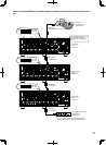
The "Unit address" setting on the
[PS·Data setup] tab under
"Communication" of the setup
menu
Monitor 2
First recorder
System: 1
Controller: 1
Third recorder
System: 3
Controller: 3
Second recorder
System: 2
Controller: 2
Fifth recorder
System: 5
Controller: 5
Fourth recorder
System: 4
Controller: 4
HDMI cable
(sold separately)