


18
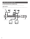
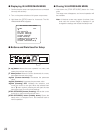
■ Serial Port Connections
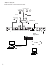
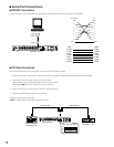
● RS232C Connection
A 9-pin connector is provided with the recorder to communicate with the PC based on the RS232C.
● PS
•
Data Connection
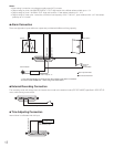
Note the following when connecting the recorder with the PS
•
Data devices.
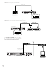
1. Place the recorder in the middle of the chain when the System Controller and other devices are connected.
2. Termination must be made at both ends of the chain.
Refer to the manual included with each device for termination.
See page 20, ■ DATA Port Termination for the recorder.
3. Protocol selection must be set to PS
•
DATA in the menu setup.
4. Use the optional RS-485 cable for connection.
Connection examples are shown.
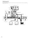
<Case 1 > With System Controller and other devices
SIGNALGND
POWER
DATA10/100BASE-TMODERS-232C
MULTI
SCREEN OUT
SPOT
OUT
1
1
ALARM/REMOTE
OFF
ON
2
2
3
3
4
4
5
5
6
6
7
7
8
8
OUT
VIDEO
OUT
AUDI O
IN
IN
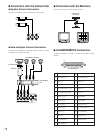
Personal Computer
Digital Disk Recorder
D-sub9
D-sub9
or
D-sub25
4 (ER)
5 (GND)
3 (TXD)
6 (DR)
7 (RTS)
8 (CTS)
2 (RXD)
6 (DR)
7 (GND)
3 (RXD)
20 (ER)
5 (CTS)
4 (RTS)
2 (TXD)
PC
DB25
WJ-HD200
DB9
1
2
3
4
5
6
7
8
Frame
1
2
3
4
5
6
7
8
Frame
Shield
WJ-HD200
DB9
PC
DB9
RS-485 Cable
POWER
ON
OFF
ALARM
Data Multiplex Unit WJ-MP204
ALARM
SUSPEND
1234
ESCSET
RESET
SUSPEND SET UP
ALARM
UNIT
0
9
8
7
6
5
4
3
2
1
RS-485 Cable
System Controller
Disk Recorder
System Controller
Termination : ON
Data Multiplex Unit
Termination : ON
SIGNALGND
POWER
DATA10/100BASE-TMODERS-232C
MULTI
SCREEN OUT
SPOT
OUT
1
1
ALARM/REMOTE
OFF
ON
2
2
3
3
4
4
5
5
6
6
7
7
8
8
OUT
VIDEO
OUT
AUDIO
IN
IN
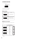
(#5 : OFF, #6 : OFF)
DIP Switch
MODE
1 2 3 4 5 6
ON